
The docuRob® WorkFlow process modeler product provides the work environment of the process architect*,* supporting modelling and development of graphical process models compliant with the guidelines of the OMG BPMN v. 2 standard. In accordance with the adopted design methodology, the tool can be used in individual phases of the project life cycle from the conceptual process model to its executable definition.
The executable process definition is maintained within the process repository integrated with the docuRob® WorkFlow execution platform*.* The process definition repository provides flexible management of the process models that supports versioning of definitions and the controlled release of process definitions into operation. The platform allows simultaneous processing of processes initiated on the basis of different versions of their definitions.
In the following sections of the chapter we discuss individual classes of process model objects (flow objects) used to create subsequent levels of the process model.
Process Definition
Process Definition is a complete representation of a process that enables its execution by a workflow management system. The process definition concerns various aspects of the process, in particular: control flow, data flow, and assignment of work participants, as well as execution of applications within an activity.
Modifying a process definition creates a new version. Multiple versions of the same process can exist (and be executed) at any given time, but only one is the most current, available, and it will be used for all newly started processes. A process definition can also be part of another, more complex process.
A process (its definition) may require input parameters and produce the results of execution in the form of output parameters. The tabs of the process definition screen are presented in Figure 1.
Name is a unique identifier of a process definition within a given docuRob®WorkFlow installation, with the subsequent versions of the definition being identified by integers starting from 1.
The priority determines the execution priority for all process instances started at the level of this definition. The priority can be defined both at the process level and at the definition level activities. The default value of the indicator is 100 and its maximum value is 2147483647. A process definition called as a subprocess can inherit the priority of the corresponding compound activity or
The Process owner tab identifies the person responsible for its maintenance and operation and usually also for all aspects related to the business activity it supports. Users acting in this role receive all the standard messages regarding exception conditions.
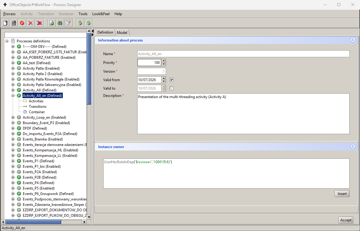
Figure 1. Process definition tabs
Activities
An activity is a work unit that specifies a single step within a process. An activity can be atomic, compound, or control. An atomic activity is defined as a task, a compound activity as a subprocess, and a control activity as a gate.
The order of workflow between activities is defined by the type and conditions of the selection of the appropriate flow. Each activity can have preceding activities and immediately following activities.
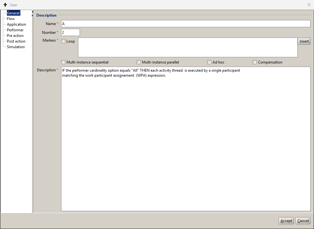
Figure 2. Activity definition tabs
Within the Performer, Post-action and Pre-action tabs there exists a BPQL expression helper, available via the Insert tab*,* which supports the selection of appropriate expression elements from the provided dictionaries (see Figure 3.).
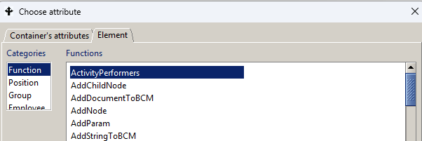
Figure 3. BPQL Expression Helper
Selection of the process execution path is based on the definition of the configuration of incoming and outgoing flows from activities or gateways. The instantiation of process graph elements involves the use of tokens flowing between them or in the case of events on generating or receiving event triggers. The concept of a token was introduced as an intuitive illustration of the mechanism for transferring control between elements of a process graph.
Logical dependencies between incoming flows within the activity metadata allows for adopting the desired instantiation discipline for a given process graph element and, in the case of outgoing flows, for selecting the succeeding path of the token flow. The definitions of the join and the split flow discipline are shown in Figure 4.
Joining of input control of multiple incoming flows, or in other words handling of multiple tokens incoming to an activity, depends on the specified operator causing for:
- AND operator instantiates actions after tokens have been entered by all incoming flows
- OR operator instantiates actions after tokens have entered all incoming flows that meet the conditional expressions defined for them
- XOR operator instantiates activities after any of the incoming flows receives the first token.
Control flow of multiple outgoing flows, or in other words handling of multiple outgoing tokens from an activity, depends on the specified operator causing for:
- AND operator sending tokens through all outgoing flows
- OR operator sending tokens by all outgoing flows that satisfy the conditional expressions defined for them
- XOR operator sending tokens via the first outgoing flow that satisfies the conditional expression defined for it or it is not constrained by any condition
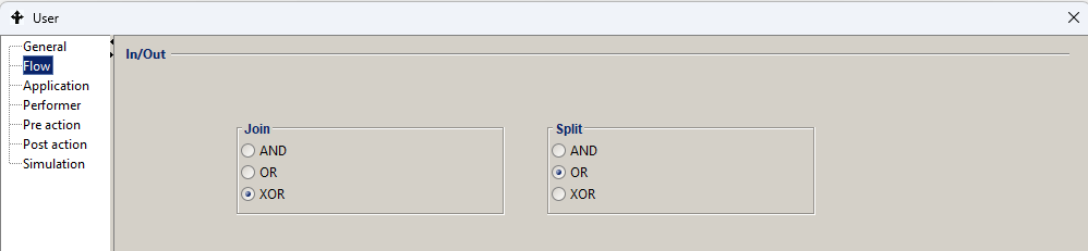
Figure 4. Join and split flow parameters
An alternative technique for controlling selection of a process path are gateways, which, in addition to providing greater flexibility in the selection of a process path, are essential elements of the conceptual process model. Flow control using gateways is described in detail in the following sections of the documentation. Because of their visibility in the process/subprocess graph*, gateways* are the preferred technique for defining branches, at least at the level of the conceptual process model.
Regardless of the type and kind of an action, the capability of executing a BPQL script or an external application has been introduced*,* both before its execution (Pre-action) and after its execution (Post-action). The interfaces for entering a BPQL script are shown in Figure 5 and Figure 6 respectively.
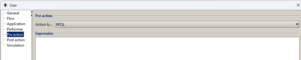
Figure 5. Pre-action Definition activities
Actions allow for:
-
performing additional actions on process input and output parameters, global variables or parameters of the application called in the activity (e.g. setting status, adding a value to the loop counter, etc.)
-
invoking additional applications before starting and at the end of an activity.
Actions are performed:
-
when an activity is assigned to a given performer. This action is called preaction.
-
at the completion time of the activity (does not apply to interrupting of the activity). This action is called postaction.
An action is represented as a BPQL expression or as an invoked application. In the case of the BPQL rule, unlike the participant assignment or a flow condition, there are no restrictions on the value returned by the BPQL rule executed in the action.
Actions are most often used to properly prepare input and output parameters of the application called in the activity. Another application of the action is to use it to set the values of process data represented by global variables.
To define the Preaction you need to:
- in the process list panel, click on the process in question,
- go to the ’Model’ tab of the process in the right panel. Find the right activity and double-click*.* The activity properties dialog will appear on the screen,
- click on the Pre action node.
- Select the appropriate Action Type.
- If the selected type is BPQL – the appropriate BPQL rule must be defined*.* If the application has been selected*,* then the specification of its invocation must be provided as required by the interface of the application.
For the Pre-Action script, it is additionally possible to execute it in whole or in part before execution of the activity instance by marking it as a @beforePreAction BPQL block*.*
The code contained in this block, unlike the rest of the Pre-action, will be executed during the creation of the activity instance. In a situation where ALL is defined for performers of a given activity, the @beforePreAction block will be executed n times during the creation of the activity (n instances of the activity are created*),* while the remaining part of the pre-action will be executed once, immediately before the activity is executed.
The postaction is defined in a similar way by selecting the Post-action tab..
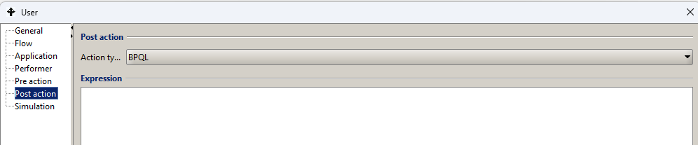
Figure 6. Definition of Post-action activity
In the case of complex processes with high variability of use case types, an important element of the process environment definition is to designate appropriate human resources for User type tasks. One of the elements of parameterization of the Analytical Simulator used for this purpose is to determine the performance parameters of each activity*.*
Figure 7 presents the interface for describing such activity performance parameters as the number of potential participants and the average task completion time. Optionally, you can also provide the average task completion costs.
Analytical Simulator algorithm and an example of its application in process design and management is available in the section on process monitoring and analysis.

Figure 7. Analytical simulator parameters for the activity
Task
A task is an indivisible element of the model, unlike a subprocess, which may contain an arbitrarily complex model comprising many elements. Task types, along with their graphic symbols and description of the activity, are presented in Table 1.
| Symbol | Name | Description |
|---|---|---|
 | Message | Task sends a message containing metadata and the message content via the invoked communication application (e-mail, electronic messenger, SMS). The parameters placed in the process container are transferred to the communication Application in accordance with the requirements adopted for the Service type task. |
 | Reception | Task listens for a trigger thrown by its corresponding throwing task Message. Handling the message requires invoking an appropriate application that is compatible with the application used in the throwing task. In the case of an event-based gateway the task appears as one of the events indicating the outgoing flow. |
 | User | The task participant is an authorized User who has received information about a new task on his task list. The interface, along with the appropriate services, is provided by an application called by the workflow engine. The docuRob®WorkFlow engine supports the user interface via an integrated electronic forms module invoked by default as a standard application provided a form is defined for the process type. The assignment of a task to one or more users is controlled by the BPQL script that uses such features of potential performers as authorizations, competences, position and function in the organizational structure or a role in the business process. |
 | Manual | The task is made available via the task list to the appropriate user or users but it is not managed in any way by the workflow engine except for indicating time points including start and end times |
 | Business rule | The task performed automatically based on BPQL conditional expressions. Conditional expressions contain global process variables, local script variables, data from external databases and/or elements of XML files. The result of the operation is setting the values of the appropriate global process variables. |
 | Service | The task is performed by an available Web Service or by an Application called directly by the workflow engine. The called applications are responsible for handling the user interface and can be implemented in any programming language. |
 | Script | The task is performed by a BPQL script operating on the process container data, the process ontology variables, and the external data sources. |
Table 1. Task object types.
Application call specification defines how a given application is to be invoked within a task. This also includes specifying rules for mapping input and output parameters of a subprocess.
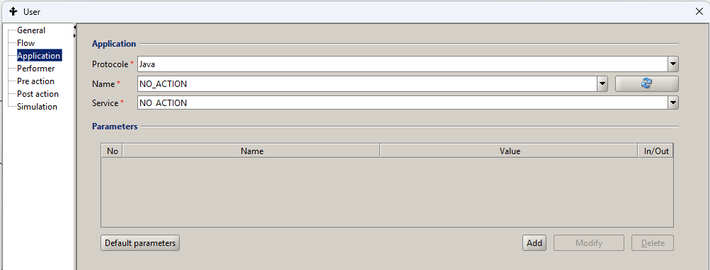
Figure 8. Definition of parameters of the Application handling the task object
The Application Parameter Mapping (Table 2) specifies how to:
- assign values to the application input parameters processed by the target activity,
- assign a global variable to which the results of the activity application execution will be passed*.*
The BPQL rules are used to define the mappings. The attributes of the parameter mappings are described in Table 2.
The Application Definition is required for User and Service task types and it is optional for the Activity types Message and Reception as well as Business Rules. In the first case, it is possible to use external application (e-mail, SMS gateway, messenger) and in the second case, in addition to the BPQL rules, one can use an external rule engine such as for example Drools.
| Attribute name | Attribute description |
|---|---|
| id | Mapping identifier. |
| Name | The name of the application attribute to which the mapping applies. |
| Value | A BPQL rule representing a mapped value. |
Table 2. Application parameter mapping attribute specification

Figure 9. Application parameter value mapping form
The docuRob®WorkFlow system supports three call protocols:
- Java – the application implements the external application interface defined in the docuRob® WorkFlow system and it is implemented as a Java class. This protocol works only in the synchronous mode. The service field specifies the full location of the class (packages and class name). The protocol may also be used to call the REST service connector.
- URL – the application is invoked using the URL link available via the HTTP protocol. This protocol is primarily characterized by invoking an action and works only in the synchronous mode. The Service field specifies the invocation address. This protocol is also used to invoke the REST (Representational State Transfer*) web services*.
- WebService – an application is a web service that provides one or more operations. The application specification can be downloaded from a UDDI server (Universal Description, Discovery and Integration) or directly from a WSDL file. After reading the specification of a given service, a list of input and output parameters is automatically loaded. This protocol characterizes the invocation of an automatic action and works in the asynchronous mode. The Name field specifies the name of the service and the Service field specifies the name of the invoked operation in this service. The service specification can used by the SOAP or REST protocols.
- The REST web service connector is used mostly to access external applications integrated by the docuRob® platform.
The standard User task
The User task may invoke any external application, accessible via the Java protocol, exposing the graphic user interface. In most cases the docuRob® users select the platform native tools, such as the ObjectManager and the electronic forms defined and processed by the eForms product. The latter tool provides a user-friendly environment to specify and support the advanced graphical user interface used within the docuRob®WorkFlow tasks.
Figure 10 shows the use of the ObjectViewer tool supporting the graphic user interface of an authoring Task of the example publishing Group Work process presented in Figure 11.
The ObjectViewer parameters controlling the display of the selected sections of the eForms user interface provide the following control information:
- The object identifier (ObjectId) stored in the process container variable $obj.
- The usage mode of the interface sections assuming the edit, view values.
- The parameter showFormSections indicates the form sections to be presented in the current execution of the authoring task.
The authoring task is executed iteratively servicing a standard publishing procedure. Each iteration the task is displayed with a different graphic interface corresponding to the current process state.
The BPQL rules controlling the presentations of the Author report task GUI (Activity no. 5) are presented below:
IF ($step=1) THEN  {$viewOpracowanie:='Author'; }
IF ( $step=2) THEN  $viewOpracowanie:='Author, Reviewer';
IF( $step=3) THEN  $viewOpracowanie:='Author, Editor';
IF ( $step=4) THEN  $viewOpracowanie:='Author, Authorization';
$editSectionsOpracowanie:='Author';
The BPQL rules are defined in the pre-action of the Author report activity.
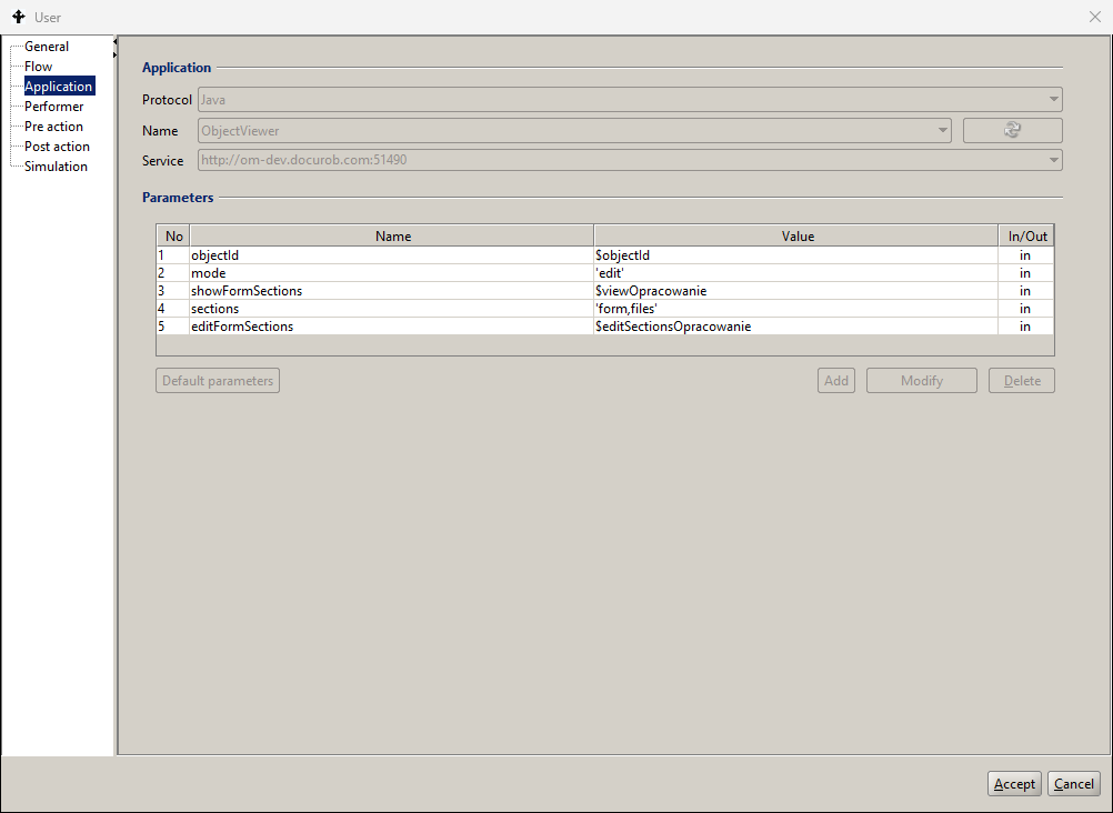
Figure 10. Definition of a standard User task GUI
The appropriate electronic form section names and presentation rules were developed as parts of the graphic interface design with the use of the docuRob® eForms product.
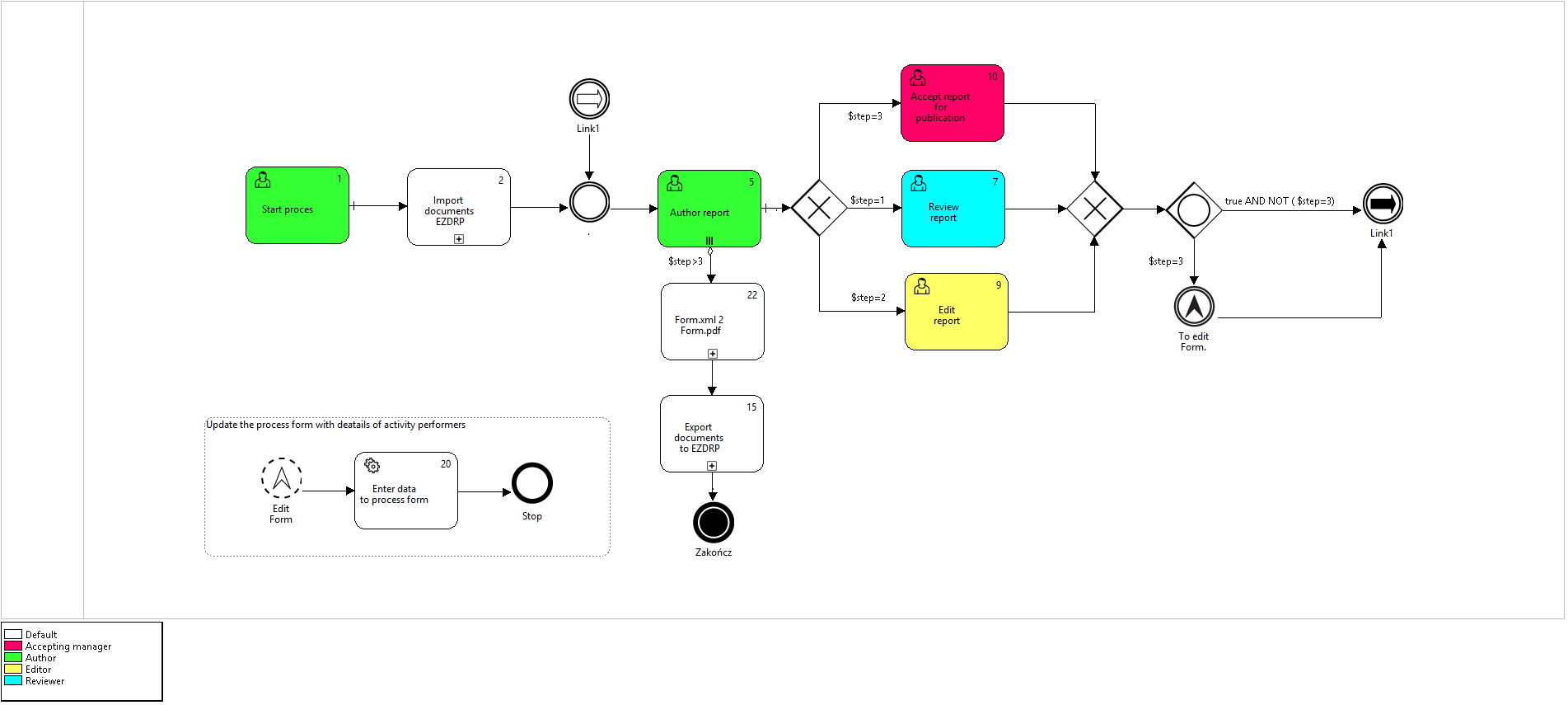
Figure 11. The BPMN 2.0 model of the Group work publishing process
The process execution history graph and the resulting electronic form converted to the pdf document shown in Figure 12 and Figure 13 respectively
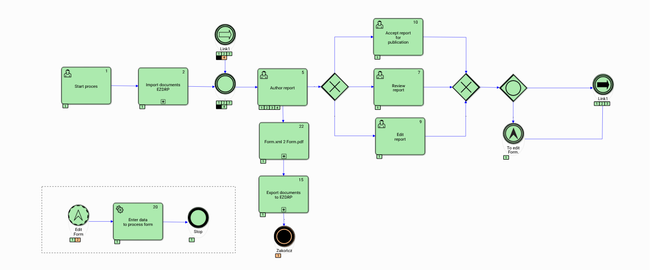
Figure 12. The history graph of the Group work publishing process

Figure 13. The resulting process form in pdf format.
Web Service Connectors
The SOAP web service
Definition of the SOAP web service invocation is presented in Figure 14 thru to Figure 20.
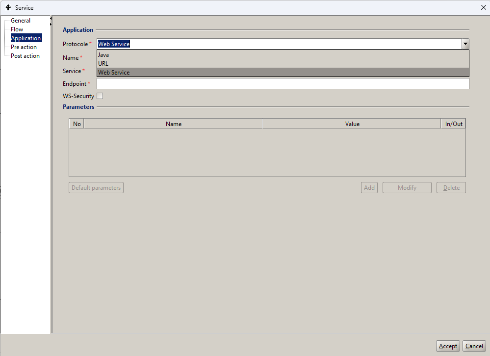
Figure 14. Example definition of Application parameters for calling the SOAP service
To specify the location of the WSDL, select the button marked with a green plus icon  .
.

Figure 15. Fragment of the Application parameter definition window for the Web Service protocol
In the interface that appears, you must enter the URL of the web service, i.e. the location of the WSDL file.

Figure 16. WSDL Location Indication Interface
Once validated, the specification contained in the WSDL is read. Then, in the Name field, select an available item with the service name.
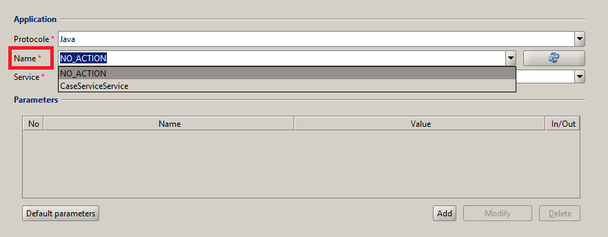
Figure 17. Service indication in the Name field
After selecting a service in the Name field, the following fields will be automatically filled in: Service, Endpoint, and the list of input and output parameters will be loaded in the Parameters table.
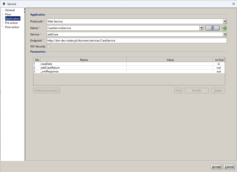
Figure 18. Example definition of Application parameters after indicating the service
In the Service field one can select one of the available services for the website.
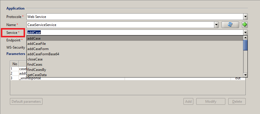
Figure 19. Selecting a service
Each time a service is selected, a list of input and output parameters is loaded. The input and output parameters of the service must be specified by filling in the Value column in the Parameters table.

Figure 20. Example definition of service parameters
The REST web service
The REST web service connector - A REST web service can be called using a predefined Java class. We call it in the JAVA protocol, specifying name and service giving the full name of the class:
pl.rodan.ooworkflow.environment.activity.CallRestService
An example of the REST service invocation updating values of the process form is shown in Figure 21.
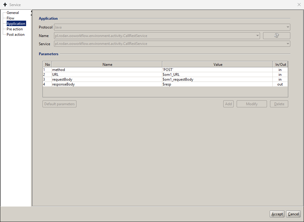
Figure 21. Example definition of connector parameters for REST service call
One must additionally specify values of the following input parameters:
- method - to specify the call method ['GET',’POST',’PUT',’DELETE']
- URL - to specify the call address along with parameters
- requestBody - to specify the call content, the JSON format should be maintained as well as the Type of the output attribute :
- responseBody - to indicate the parameter in which the response of the service call will be placed in the JSON format.
Figure 22 and Figure 23 show, respectively, the definition of the pre-action BPQL expressions setting the values of the Rest service parameters and the state of global variables in the process container.
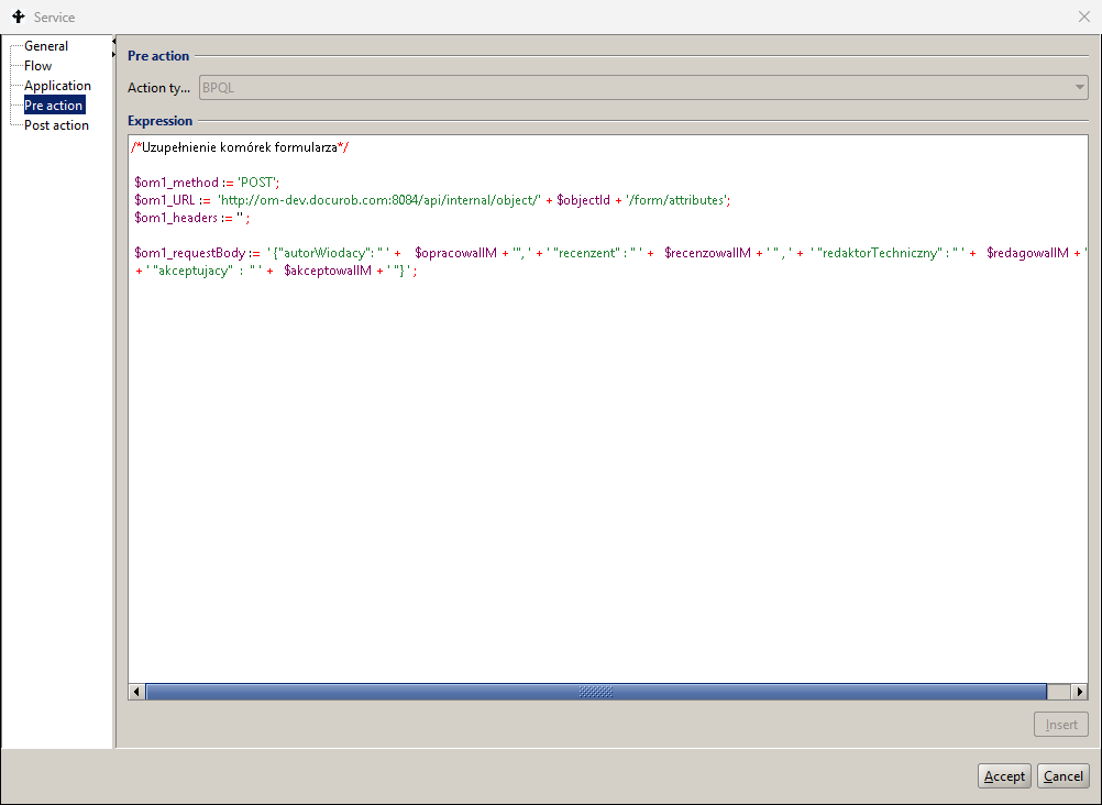
Figure 22. Expressions setting the Rest service parameter values
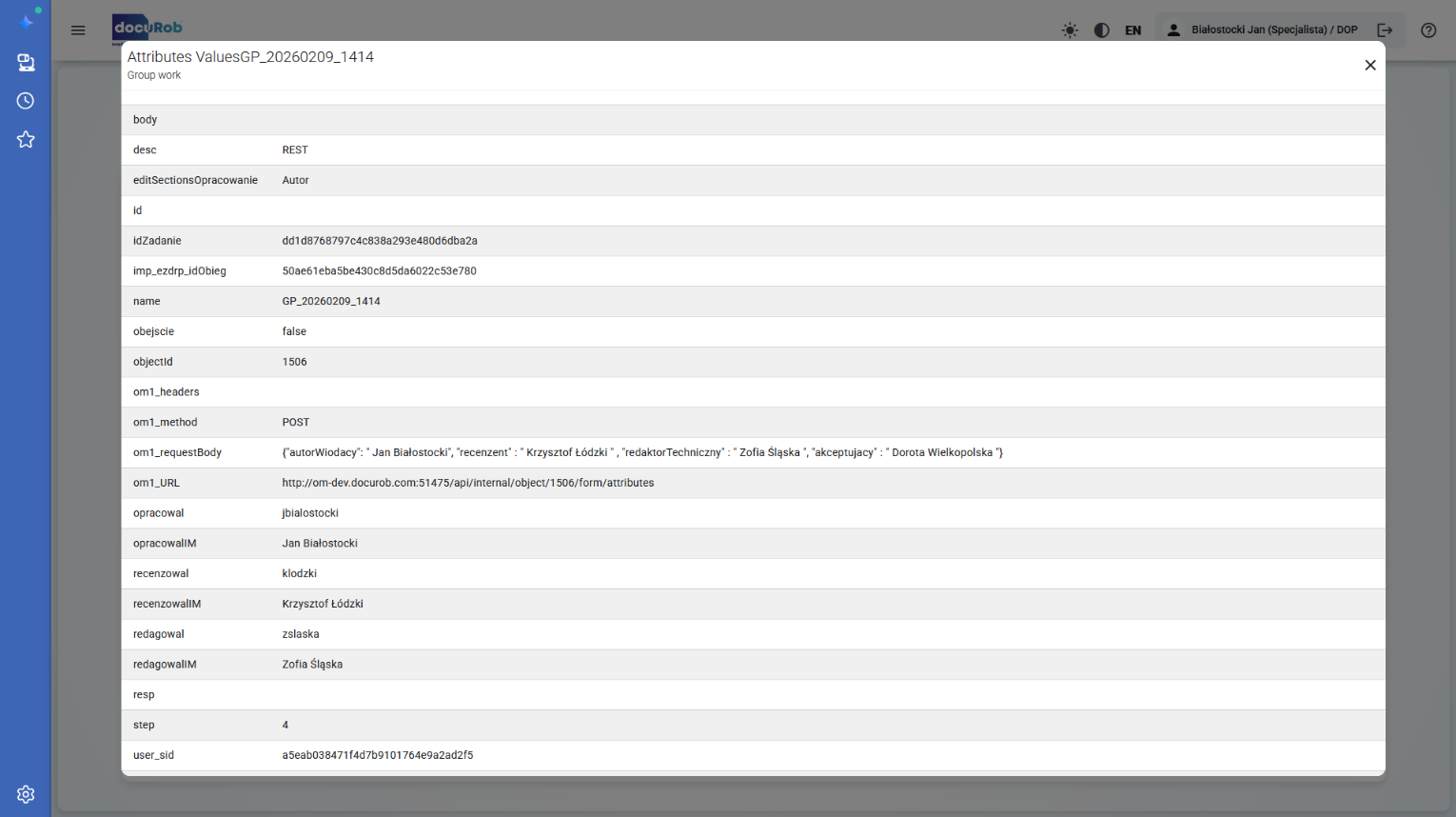
Figure 23. The state of the global variables of the process after the service is executed
Work participant assignment
Assigning a workflow participant is mandatory for tasks of the "User" and "Manual" types. Optionally, also for "Send" and "Receive" messages. BPQL expressions assign a Workflow Participant or multiple Workflow Participants to a task. The Work Participant Assignment interface is shown in Figure 24.
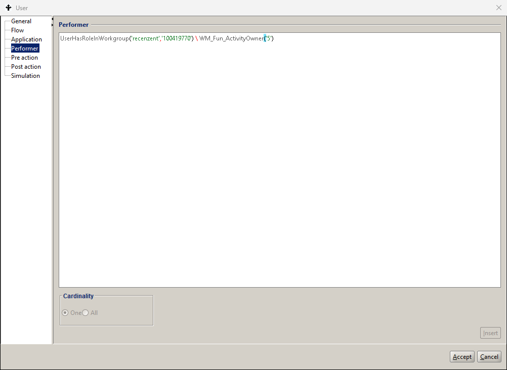
Figure 24. Definition of a Task participant.
The BPQL work participant assignment (WPA) expression indicates that the potential participant must play the “recenzent” (reviewer) role in the work group with the identifier 100419770. Additionally the rule excludes all authors of the current publication from the eligible reviewer list.
Selecting the One option means that the system will allow only one of the potential, i.e. selected by the BPQL expression, participants to perform the task at a time, after any of the participants has taken the task from the task list. The assignment algorithm is removing this task entry from the task lists of other selected users.
Selection of the All option would create task instances for all participants selected by the BPQL expression. The multi-threading task is discussed in more detail below in this section.
Subprocess
A subprocess, also called a compound activity, is a stand-alone element available within the process definition library that can be used both as a functional element of the process that includes it and/or as a stand-alone process of the highest level called by the user or an external IT system. A subprocess appears in the graph of the process that includes it as a task symbol marked in the lower line of the description with a + sign.
A classic example of such a software architecture is the process of document content recognition (Optical Character Recognition ). Recognition (OCR)), which is used to automate the recognition of various documents, for example invoices or notarial deeds, usually managed by different document flow processes. The definition of a subprocess includes its data, i.e. input and output parameters as well as global and local variables. Encapsulation of process/subprocess definitions results in complete isolation of their Data Containers.
Due to the location of the subprocess definition in the graph of the encompassing process, which creates the context of its instantiation through flow conditions, it can contain only one start event of the “None” type. Subprocesses can be nested at many levels. Communication of the nested processes is supported by the exchange of parameters.
Figure 25 showing the definition fields of the process call shared in the library of available processes listed in the process design tool, which is to be made available as a subprocess within the higher-level process being defined*.* The link between the integrated process definition and the process/subprocess calling it is made via the library name of the former.
If the called process has defined input and/or output parameters, they will be automatically placed in the parameters field in the process tab of the calling process definition. For each of the parameters placed on the list, a BPQL expression using global variables should be added. This will create a mechanism for passing parameter values between the higher-level process and the subprocess.
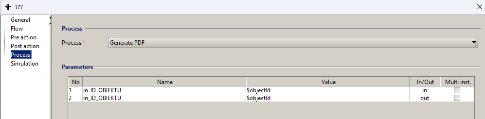
Figure 25. Calling an available process that handles a given subprocess
To define a new process input or output parameter in the process design tool:
- go to a given process in the process definition list panel
- go to the Container node, the right pane will display a list of currently defined process container attributes
- Select the menu item Container -> Add
- Enter parameter data, including:
- Name – provide a unique name. Basically, a string of alphanumeric characters starting with a lowercase letter is provided as the name. Each new word is appended to the existing ones and starts with a capital letter.
- Type – for the input parameter, select the value in. For the output parameter – the value out. If the given input parameter is also used as an output parameter (result), set the Type to in/out.
- Read Only – indicates that the parameter will be used only to read data and an error will occur when trying to write it. In the case of an input parameter, this parameter is automatically set to Read Only. In the case of an output parameter, this parameter should be left unchecked.
- Type - type of the attribute, select the appropriate type from the list of available types.
- Multi-value – if the parameter takes multiple values, this box should be checked,
- Mandatory – if the attribute value is always required, then this field should be checked. From a practical point of view, this option only makes sense for input parameters because most often the output parameter value is not known at the start of the process.
Event-based subprocess
The Event-based subprocesses are not related to the flow structure of the process that includes them. This means that such a subprocess is a separate graph placed within the model of the process/subprocess that includes it*.* The graph of an event-based subprocess is surrounded by a named box with a dotted line and cannot be the source or destination of any Flow. Within the model of such a subprocess, all flow objects specified in BPMN 2. notation may appear, but it may not have the boundary events.
An event-based subprocess can contain only one starting catching event, which listens for its corresponding throwing event from the moment the enclosing process is instantiated.
Depending on the symbol used in the model, events may or may not interrupt the execution of the process/subprocess instance surrounding the subprocess they initiate. Instance of a subprocess may only occur when the surrounding process/subprocess is active, and it may occur multiple times, resulting in the creation of the multiple concurrent instances.
An instance of the event-based subprocess is created for each of the concurrent events in the case of the non-interrupting catching events. Due to their location within the scope of the invoking process/subprocess the event-based subprocesses have access to the context of the enclosing process/subprocess. Execution of the enclosing process/subprocess is concurrent to the running instances of the event-based subprocesses.
Starting interrupting events always instantiate only one instance of the event-based subprocess. The context of the enclosing interrupted process/subprocess is available to the event handler during the completion phase to allow the event-based subprocess to be completed.
The definition of a non-interrupting event-based subprocess is shown in Figure 11 in the context of the Group work process model.
An event-based subprocess may optionally re-trigger the event that triggered it to continue its handling outside of its surrounding process/subprocess via its appropriate boundary event.
Gateways
The Control activity is an element of the control flow definition used to perform activities concurrently, alternatively or optionally. When modeling a process we have two groups of gateways at our disposal*;* namely, the split flow gateways generating one or more tokens and controlling their ensuing flow and the join gateways receiving one or more tokens and generating one token.
Split gateways
A gateway is used to separate control. In the token terms, a gate consumes one token and generates one or more tokens depending on the type of the operator. The graphical representation of an operator is the bold boundaries of the diamond on the left. The operation of the flow gateways is described in Table 3.
| Symbol | Name | Description |
|---|---|---|
 | Event-based gateway | The gateway configuration, unlike other types, does not depend on the values of the flow conditions defined in it. Its flow control depends on the configuration of events placed at the target ends of its outgoing flows.. |
 | AND Split gateway | The gateway creates multiple parallel paths by generating tokens according to the number of its outgoing flows without checking any conditional expressions. |
 | XOR flow gateway (XOR Split) | The Gateway creates one of the alternative paths within the configuration of its outgoing flows. The selected outgoing flow must satisfy the conditional expression assigned to it*.* If none of its outgoing flows satisfy the above requirement, the token is sent via the default outgoing flow if one is included in the Gateway configuration. |
 | OR flow gateway (OR Split) | The gateway creates multiple alternative paths as part of the configuration of its outgoing flows. The selected outgoing flow must satisfy the conditional expression assigned to it*.* If none of its outgoing flows satisfy the above requirement, the token is sent on the default outgoing flow, if one has been created. |
 | Complex flow gateway ( Complex Split) | The gateway generates at least one token for the selected outgoing flow of the gateway and at most one token for each outgoing flow. Both the selection of the appropriate outgoing flows and generation of tokens are executed by the BPQL expression created by the process designer. |
Table 3. Types of flow operators
Join gateways
The join gateway is used to join the flows. In terms of tokens, this operator consumes one or more tokens, depending on the type of operator and generates one token. There are three types of Gateways: AND Join, OR Join and XOR Join. The graphical representation of the operator is the bold boundaries of the diamond on the right. The operation of the join gateways is described in Table 4.
| Symbol | Name | Description |
|---|---|---|
 | AND gateway (AND Join ) | Tokens arriving on incoming flows to a parallel AND gateway are converted into one token sent on its outgoing flow only after all of them have been received. |
 | XOR Merge Gate ( XOR Join ) | Tokens satisfying the transition conditions arriving by incoming flows to an exclusive or merge (XOR) gateway are swapped for one token sent by its outgoing flow after receiving at least one of the incoming tokens. |
 | OR connection gate (OR Join ) | Tokens satisfying the transition conditions arriving on incoming flows to a merge (OR) gateway are converted into one token sent on its outgoing flow after all sent to it are received. |
Table 4. Types of join operators
Flows
A flow is a link between two activities indicating the order in which they are to be executed. A transition may have a condition. A conditional expression is defined as a BPQL rule. A flow activity is symbolically interpreted as a message in form of a token between activities*.* The condition for a flow activity that has conditional expressions is that they return the true value. The Flow Types are presented Table 5.
| Symbol | Name | Description |
|---|---|---|
 | Flow (eng. Sequence) flow ) | The flow may or may not contain a conditional expression that controls the passing of the token between activities. |
 | Flow coming out of a task with a condition | A flow exiting a task is marked with a diamond if it contains a condition definition. |
 | Default flow | An implicit flow passes the token between activities if the conditional expressions of all outgoing flows of a task evaluate to false. |
Table 5. Types of flows
The Flow definition panel (Figure 26) includes all of the elements necessary to execute it. Source and target activities are optionally identified by name and automatically by activity number in the process/subprocess graph.
The conditional expression symbolically controlling the transfer of the token is created in BPQL and is supported by the language expression editor according to the general rules adopted in the system. The condition is ignored if the flow has been marked with the Default checkbox*.*
The default flow marked with the appropriate checkbox is executed if all other transitions cannot be run due to the conditional expressions accepted in them.
Flow conditions are logical expressions that determine whether a given flow will be executed or not. A condition is represented by a BPQL rule and can contain arbitrary language elements that ultimately evaluate to a Boolean type. In practice, a control flow condition is defined based on the global process variables and BPQL functions that provide data on objects and forms evaluated by the process.
To define a condition, one must be on the Process Model tab*,* select the appropriate flow and double-click with the left mouse button. A dialog box for entering flow attributes appears on the screen. providing the following information:
- From activity – the number and name of the starting activity from which the flow is defined. Read-only value.
- To activity – the number and name of the target activity to which the flow is defined. Read-only value.
- Name –the name of the flow. This name appears in the Process Model tab.
- Description – additional information about the flow provided for documentation purposes.
- Condition – the BPQL expression.
When defining the flow condition, it is possible to insert logical operators: AND, OR, NOT using the buttons located in the lower left part of the window. To select a global variable or a built-in BPQL function, click the "Insert" button. A standard window for entering information about the organizational structure, built-in functions and global variables appears on the screen. In the Element tab*,* you can select four data categories:
- Function – a list of BPQL functions that can be used to define a condition appears on the screen. A function is selected by double-clicking on its name or by selecting the function and clicking the Select button
- Position – provides a list of employe positions defined in the system. This list may vary depending on the dictionaries supporting the use case model.
- Group – allows one to model a functional group or organizational unit defined in the docuRob® WorkFlow system or synchronized with the appropriate employee management system.
- Employee - a list of employees employed in a given group or organizational unit selected from the drop-down list of groups and units.
Selection of the global variables is done on the Container’s attributes tab. After selecting it, a list of available attributes is displayed along with information about the type and kind of the variable. Double-clicking on a given variable selects it.
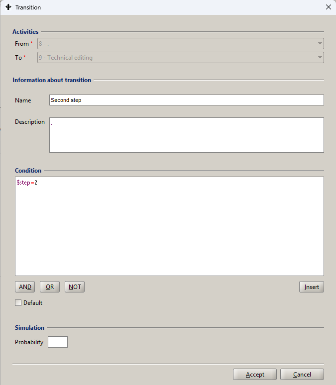
Figure 26. Flow object metadata
Other graphic symbols
The use of other graphical symbols within the process chart is discussed in Table 6.
| Symbol | Name | Description |
|---|---|---|
 | Swimlane | The intention of the BPMN 2 specification is to use the Swimlane to group tasks performed by the Process Users in a given role. For example, the Author role*.* This method of modelling in the process graph substantially complicates maintaining the readability of the model. Therefore, we have introduced an alternative marking of tasks within the Role by appropriately assigning colours to their symbols. |
 | Data object | The introduction of Data Objects and their associations with tasks is important for conveying design information at the level of the conceptual process model created in the requirements analysis phase. Due to the data handling based on the process/subprocess data container, the symbols of Data Objects and their associations are not interpreted at the process execution level. |
 | Association | The Association symbol is also used to indicate an association between a Compensation boundary event and a compensating activity. |
 | Frame | The box denotes the scope of the event-based subprocess graph placed together with its surrounding process /subprocess. |
Table 6. Other graphic symbols
Activity Kinds
Within the definition of activities, we can determine their kind by inserting appropriate activity type marker in the graphical activity symbol. Rules for their co- occurrence in the definition of an activity and the meaning are given in Table 7 and Table 8 respectively.
| marker | Co-occurring markers | ||||
|---|---|---|---|---|---|
| Single loop | Sequential loop | Parallel loop | ad hoc | Compensation | |
| Single loop | X | Y | |||
| Sequential loop | X | Y | |||
| Parallel loop | X | Y | |||
| ad hoc | X | ||||
| Compensation | Y | Y | Y | Y | X |
Table 7. Rules for using the Activity Kind Markers in activity definition
Groups of activity attributes, common to child model objects and shared through the inheritance hierarchy, are presented in this section. The remaining metadata elements are discussed in the task and subprocess sections, respectively.
General information includes elements such as the name of the activity and the activity number within the process model being created. For the activity of the type User, Service, Script, and Subprocess there are defined markers of the type of activity listed in Table 8. The Description field allows one to create activity documentation, which can optionally be made available to users of the process instance performing this task.
In the lower right corner of the form there are two function keys that allow one to:
- Approval definition of activity according to the control depth specified in the Tool Options.
- Cancel ends the activity definition
| Marker | Kind |
|---|---|
 | Single loop |
 | Multi-instance sequential loop |
 | Multi-instance parallel loop |
 | Ad-hoc |
 | Compensation |
Table 8. Markers indicating the kind of activity
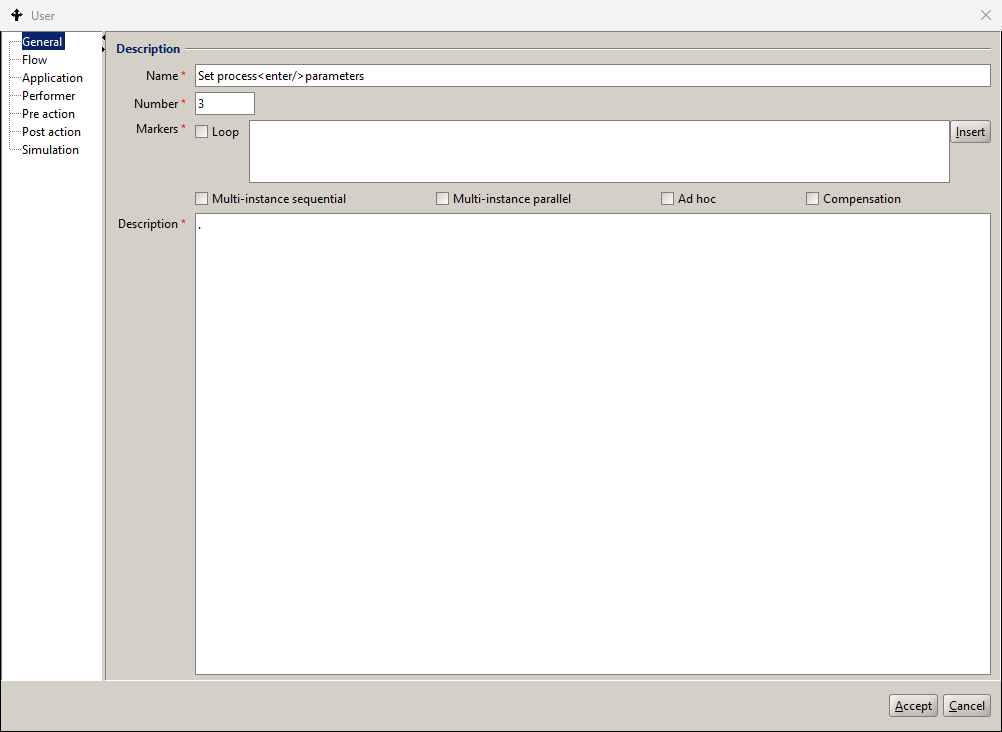
Figure 27. Definition of an activity kind
Single loop
The Single loop activity executes a predefined number of iterations of a task instantiated for a single participant. An example of the Single loop definition is presented in Figure 28.
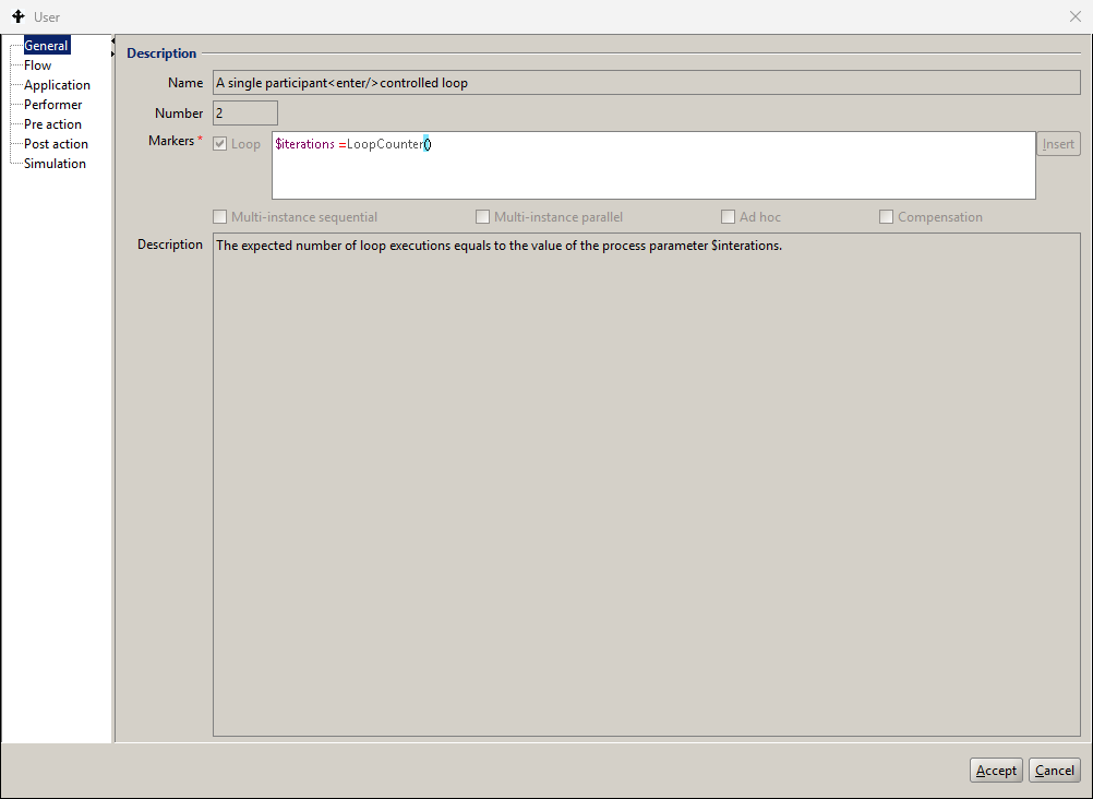
Figure 28. Definition of a single loop activity
The task iterations are controlled by a conditional expression returning the logical values true or false. The variable $iterations (integer) may be set by any activity prior to the loop. The function LoopCounter returns the value (integer) equal to the current number of loop executions’
Note, that the function LoopCounter is only available in a Single loop activity. Otherwise, the returned value is undefined. The execution history graph of an instance of the Activity Single Loop process is presented in Figure 29 and the respective list of performed tasks is shown in Figure 30.
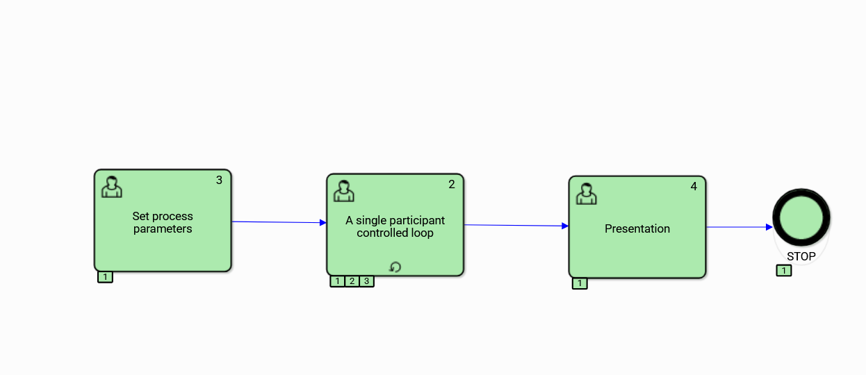
Figure 29. The execution history graph of the Activity Single Loop process
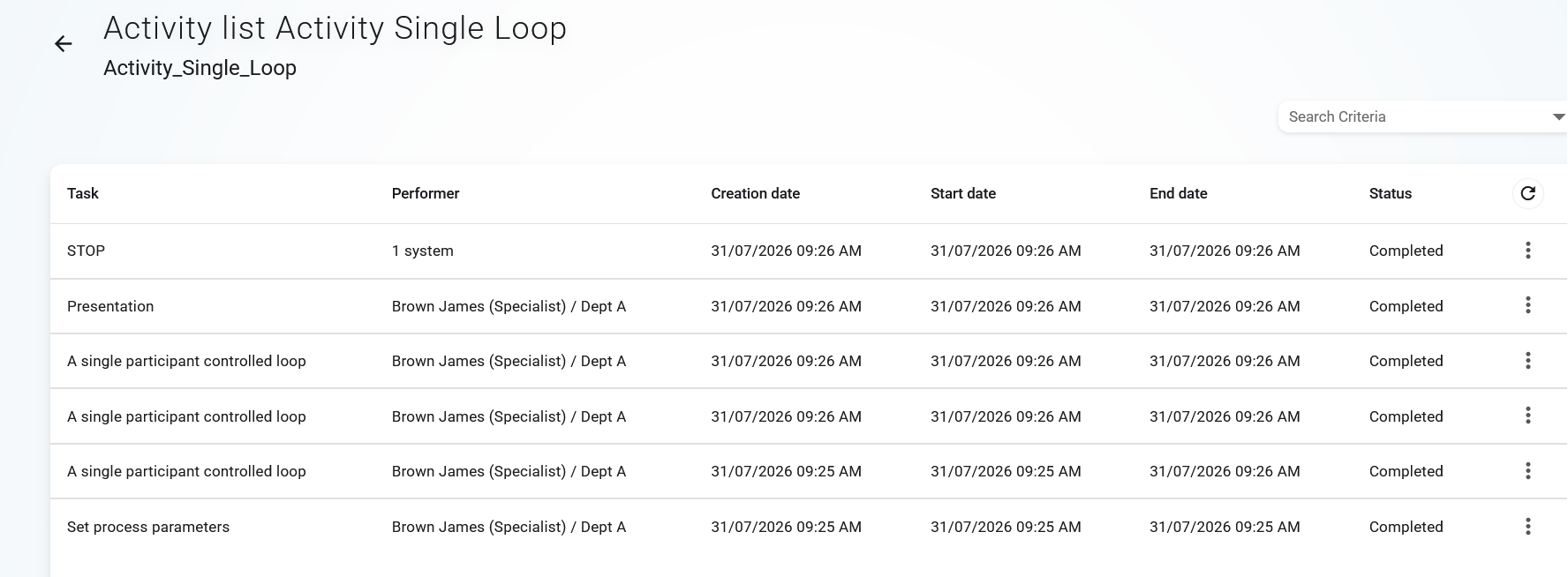
Figure 30. The list of tasks executed in a process comprising the sequential loop
Multi-instance Sequential loop
The sequential loop declaration for a multi-instance kind specifies that the processed activity instances are executed sequentially. Each instance is executed separately for each participant comprised in the result set of the BPQL expression designating the list of participants.
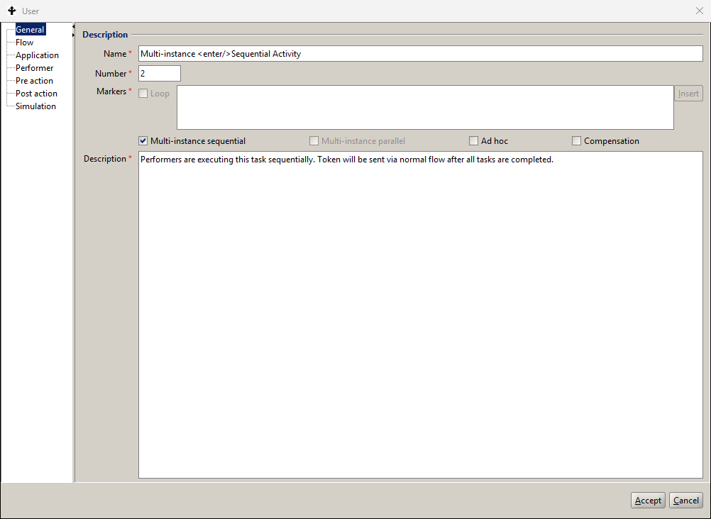
Figure 31. Definition of the Multi-instance Sequential loop Activity
The execution history graph of a process comprising the Sequential loop activity and the corresponding list of tasks are shown respectively in Figure 32 and Figure 33.
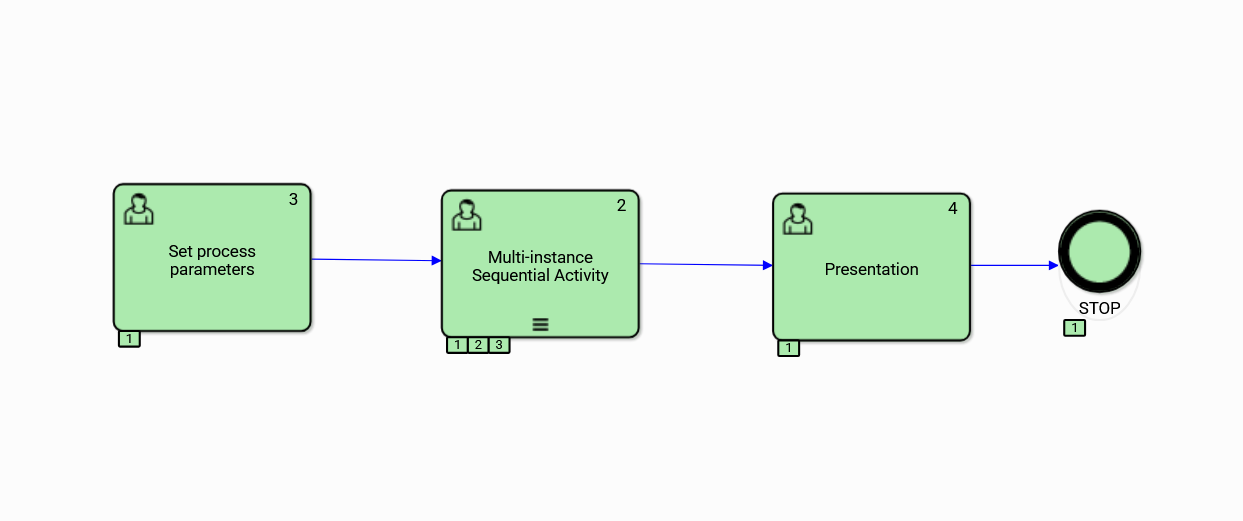
Figure 32. The execution history graph of the Multi-instance Sequential loop Activity
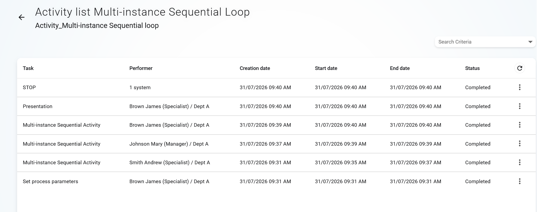
Figure 33. List of tasks executed in a process comprising the multi-instance sequential loop
The Sequential loop is executed for each participant designated by the corresponding WPA expression. The token is passed via the appropriate exit flow to the matching activity upon completion of the last loop iteration.
Multi-instance parallel loop
The a multi-instance parallel loop declaration results in concurrent execution of task instances for each of the work participants.. The instances are executed separately for each participant comprised in the result set of the BPQL expression. The token is passed via the appropriate exit flow to the matching activity upon completion of the last loop iteration.
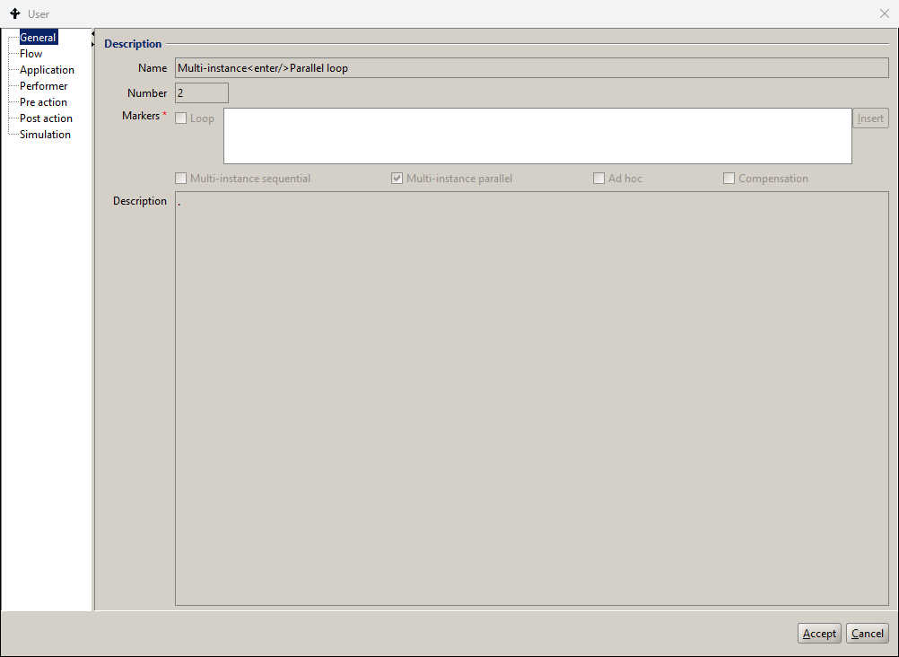
Figure 34. Definition of the Multi-instance Parallel loop Activity
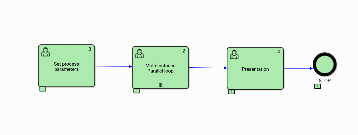
Figure 35. The execution history graph of the Multi-instance Parallel loop Activity
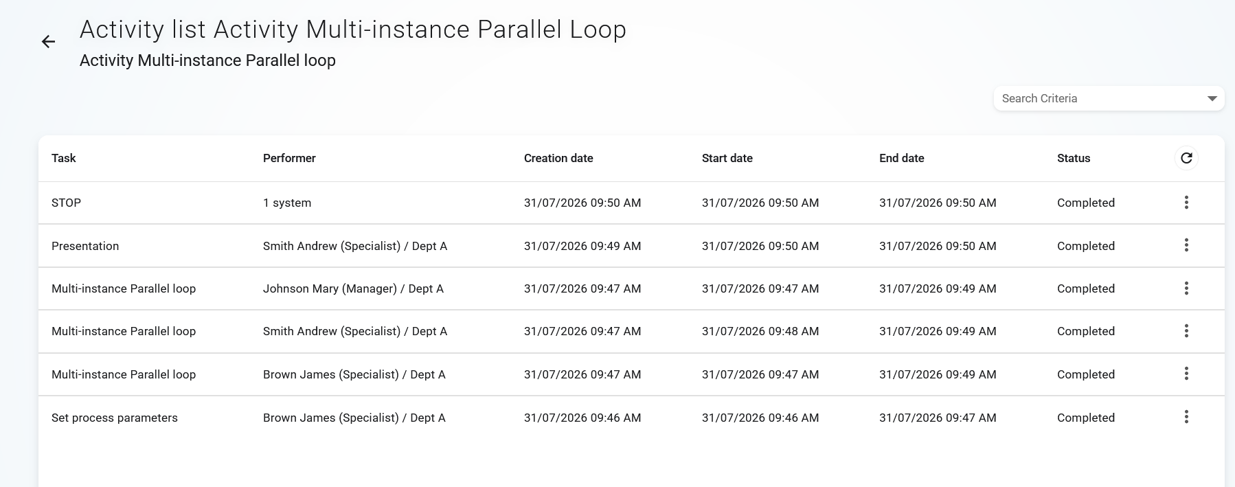
Figure 36. List of tasks executed in a process comprising the Multi-instance Parallel loop
Multi-threading activity
The multithreading activity allow for instantiation and concurrent execution of a number of tasks within the same activity receiving a token via an input flow. As opposed to the multi-instance parallel loop the completion of each task (thread) generates the token to be send via the matching exit flow. Thus each thread may activate different paths within the process graph.
Figure 37 presents the WPA expression of a multi-threading activity to be processed by all employees of the specified department. The number of activity threads must be equal to the cardinality of a participant set designated by the corresponding WPA expression. This means that each of the designated participants will receive one instance of the task.
In order at assert integrity of the WPA expression one must control the number of threads within the instantiated activity. Figure 38 presents the pre-action of the multi-threading activity shown in Figure 37 providing the number of participants required to perform the appropriate verification of the above rule. The @beforePreAction directive is executed during the activity instantiation for each task assigned to a designated performer.
The execution history graph of the process comprising the multi-threading activity A is presented in Figure 39 and the corresponding list of performed tasks in Figure 40.
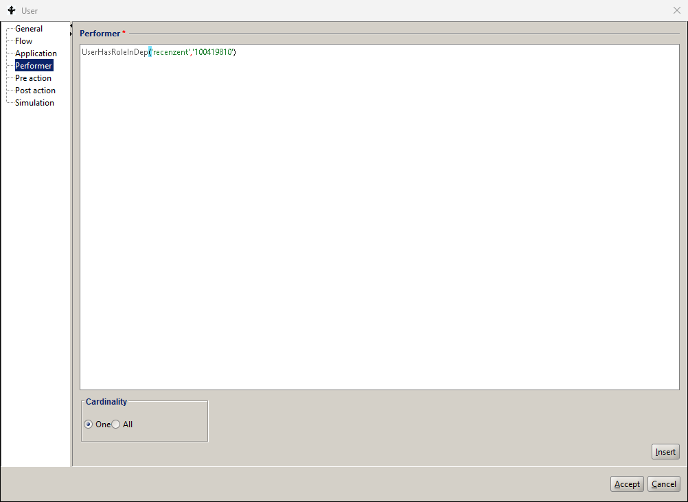
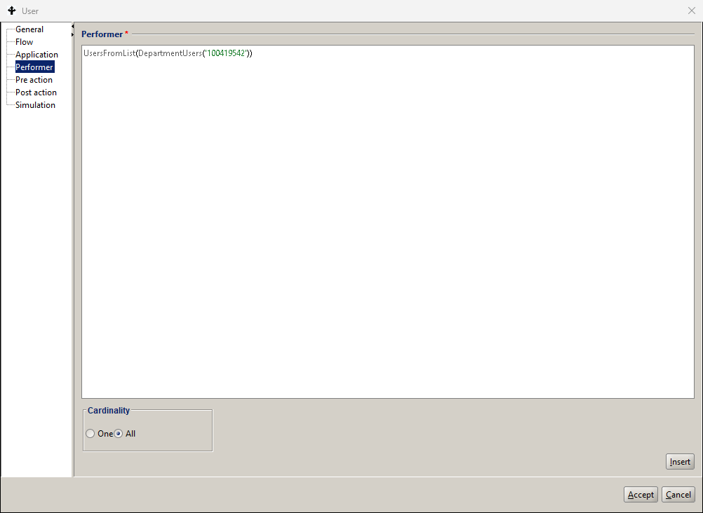
Figure 37. Definition of the Multi-threading activity
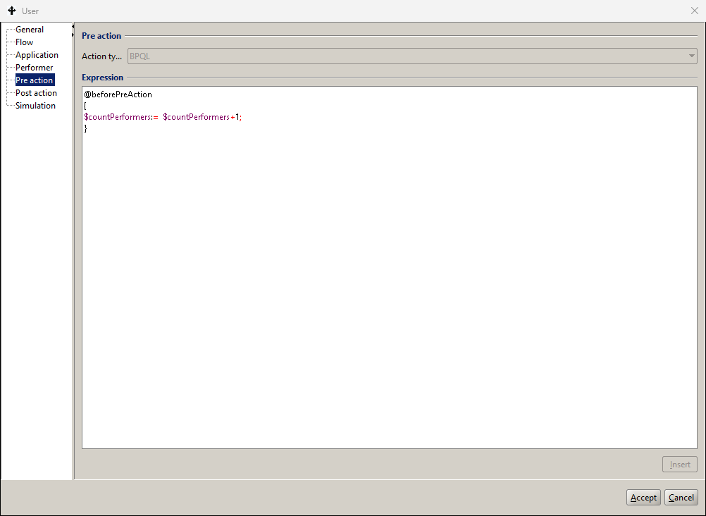
Figure 38. Setting the parameters of the Multi-threading activity
The execution history and the corresponding list of tasks of a process comprising the multi-threading activity are shown respectively in Figure 39 and Figure 40.
The number of threads created during instantiation of the activity A equals 3, which is the number of employees of the department with numeric identifier ‘100419810’. Due to the flow conditions defined for the process model 1 employee performed respectively tasks AA and BB while the remaining performers, in our case 1, followed the default flow and executed task CC.
Note that each thread of the task A generated the token subsequently sent to either the Task AA or the Task BB. The performers of these tasks were selected according to the respective WPA expressions and the joint number of task execution is equal to the number of threads generated in the Activity A.
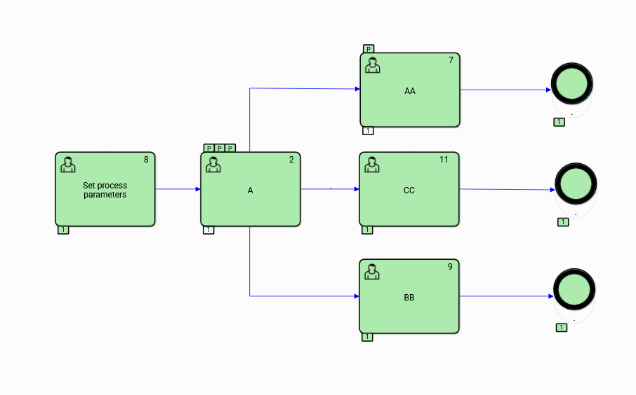
Figure 39. The execution history graph of the process comprising the Multi-threading activity
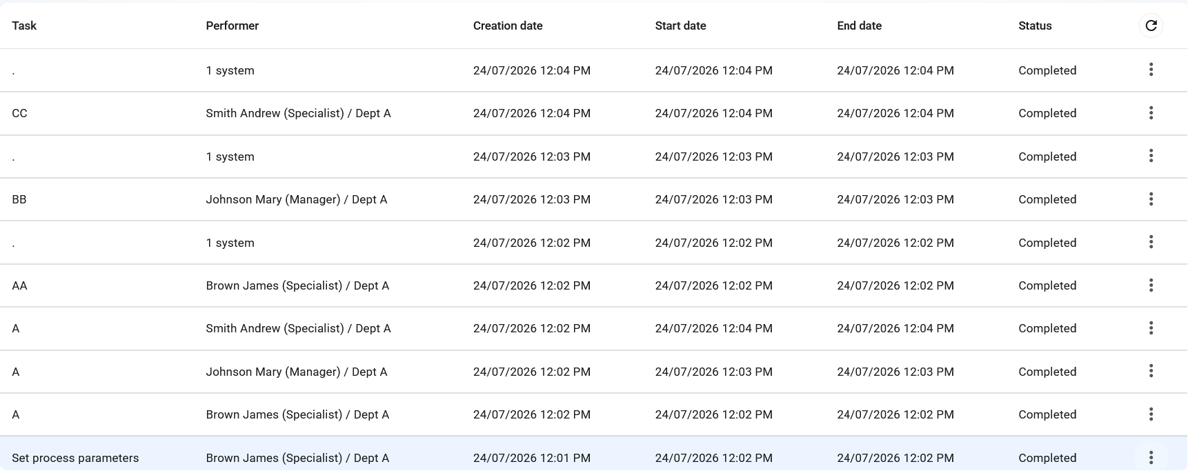
Figure 40. List of tasks executed in a process comprising the Multi-threading activity
ad hoc Task
The ad hoc Tasks may either be of the single-thread or multithread kind. The following execution control rules are applied:
- The single-thread ad hoc task may be executed by one of the designated participants. Other participants will see the on their task list when it is ready for execution.
- The multi-threading task, designated by the All option in the Performer tab of the corresponding activity specification, may be con-currently executed by performers selected by the WPA expression.
Ad hoc tasks are executed according to the following rules:
- Instantiation of the ad hoc tasks occurs at the time of the instantiation of the process/subprocess containing them*.* Tasks are either of type " User " or " Manual ". The list of participants is created according to the corresponding BPQL expression. Each of the designated Users can perform the assigned tasks multiple times*.*
- Execution of the single-thread ad hoc task instance may be finished by the "Complete" service. The Complete service is inactive for the multithreading ad hoc task instance.
- Execution of the multi-threading ad hoc task instance is automatically completed by the system when the encompassing process/subprocess is terminated.
- The multithreading ad hoc task is terminated when all of its instances have been completed.
Compensation Activity
The compensation indicator denotes an activity that reverses the effects of its related activities, i.e. a task or a subprocess. The association of the compensated activity is specified with the use of an appropriate boundary event of the type ‘compensation’ associated by an association with the compensating activity.
The condition for performing compensation is a positive completion of the reversed activity. If such a condition does not occur for the indicated activity, then compensation is not performed.
Alterative methods of modelling process flows
The presented examples are intentionally neutral from the application point of view and all activities included in it are marked with capital letters of the alphabet. The purpose of the example is to illustrate alternative methods of process modeling, i.e. control through the definition of the flow model and exercising control through logical operators provided in the Flow tab of the activity definition panel (Figure 41) or through the definition of gateway flows and connections (Figure 42).
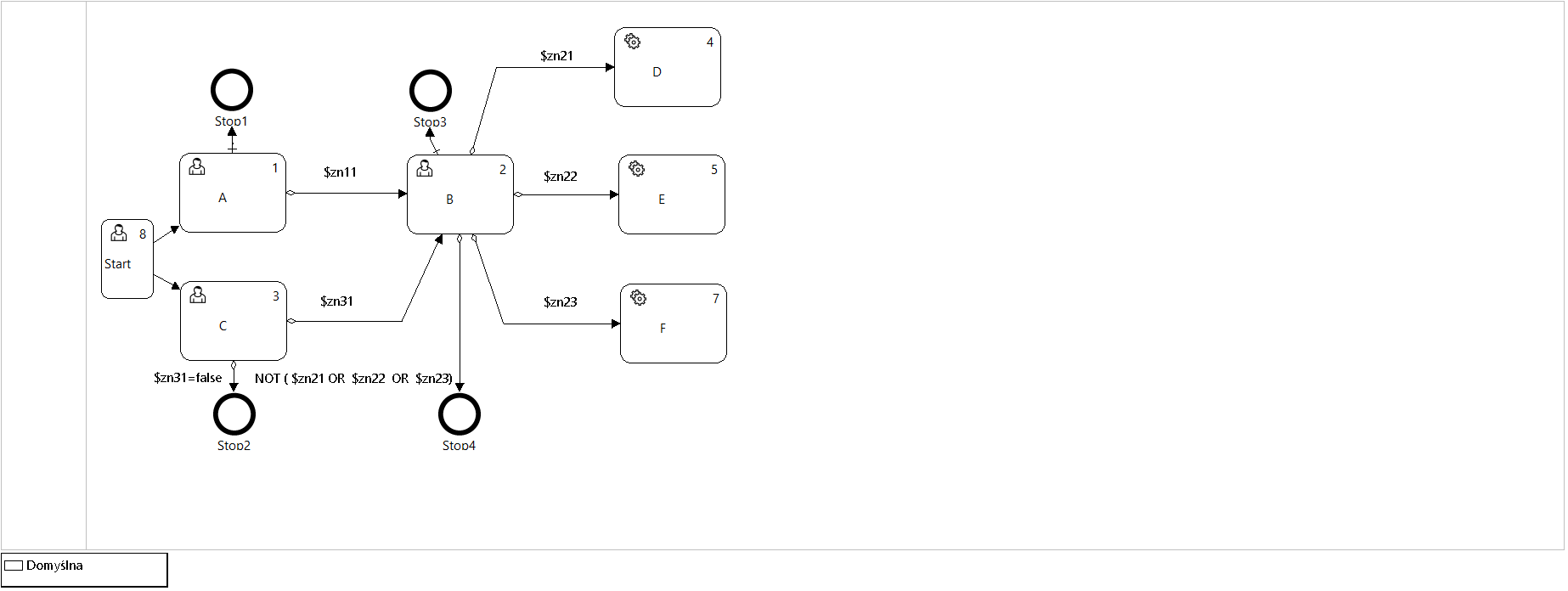
Figure 41. Process definition with flows defined in the activity metadata
The presented alternative process models are generated by the process design tool of the docuRob® WorkFlow platform. The possibility of marking the roles of performers in tasks of the type User has been intentionally omitted. Figure 43 to Figure 46 illustrate the history of the execution of four different process flow models
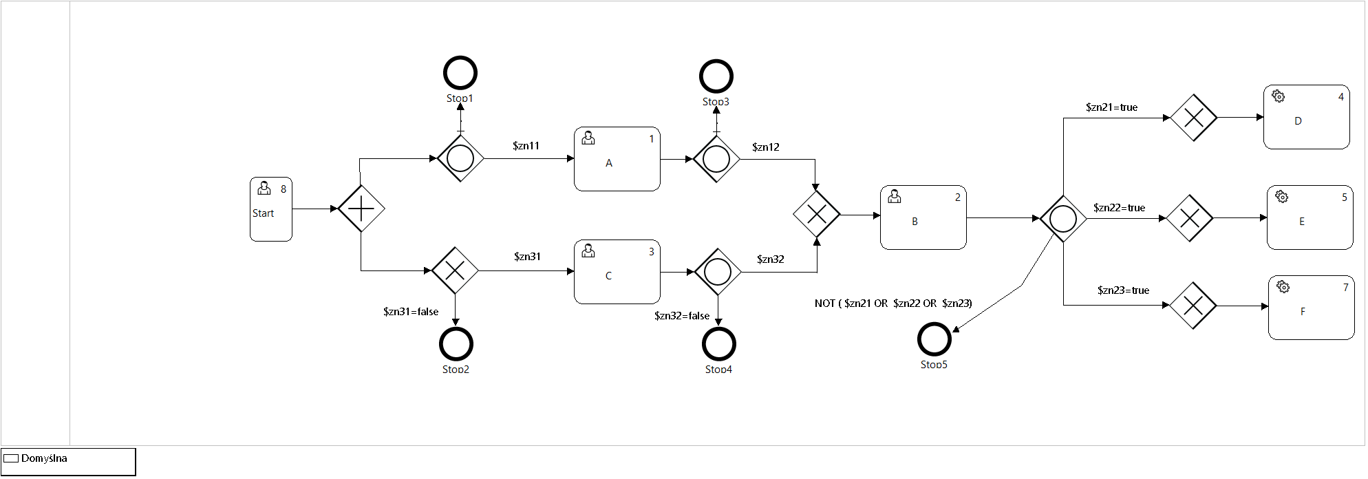
Figure 42. Process definition with flows through Gateways
The executed runs of four pairs of process instances, created based on alternative models, differ in the logical values (Boolean type) global variables controlling the flows within both instances. The differences in the setting of the logical variable values in the execution variants of models 1-4 are shown in Table 9. For the subsequent run variants, only the rows that differ in relation to run variant 1 are shown.
Run 1 (Figure 43) was executed after introducing global variables with values "true" as input parameters of the invoked instances. Both expected parallel definition instance paths (AND gate) have been executed.
The difference between variants 1 and 2 of the execution of process pairs consists in assigning the value false to the logical variable $zn11 controlling the flow between activities A and B (Figure 44) or, in the case of the model based on gateways, between the Split OR gate and activity A (Figure 45). Blocking this transition resulted in the execution of only one process path in variant 2.
| Run | Action | In | Out | zn11 | zn12 | zn31 | zn32 | zn21 | zn22 | zn23 |
|---|---|---|---|---|---|---|---|---|---|---|
| 1 | Start | XOR | AND | T | T | T | T | T | T | T |
| A | OR | OR | T | T | T | T | T | T | T | |
| C | XOR | OR | T | T | T | T | T | T | T | |
| B | XOR | OR | T | T | T | T | T | T | T | |
| D | XOR | OR | T | T | T | T | T | T | T | |
| E | XOR | OR | T | T | T | T | T | T | T | |
| F | XOR | OR | T | T | T | T | T | T | T | |
| 2 | A | OR | OR | F | T | T | T | T | T | T |
| 3 | A | OR | OR | T | F | T | T | T | T | T |
| C | XOR | OR | T | T | T | F | T | T | T | |
| 4 | E | XOR | OR | T | T | T | T | T | F | T |
Table 9. Flow condition configurations in runs 1-4.
Run variant 3, with the logical variables $zn12 and $zn32 set to false, resulted in blocking the AND flow in both models and, accordingly, terminating both parallel process instance paths after executing activity instances (tasks) A and C.
Variant of run 4, when setting the value of the logical variable $zn22 to false, will skip the execution of action E.
The purpose of the example is, among other things, to show the functional equivalence of process instances based on alternative model definitions resulting in obtaining the same task execution paths.
Choosing a graph based on control activities (gateways) is a semantically richer alternative and seems more friendly to users responsible for automating business procedures based on the process architecture (business representatives).
In the case of using an internal definition of flows, we can expect increased efficiency of processing process instances (lower load on the server configuration) due to avoiding the workload resulting from running a larger number of control activity instances. This approach is undoubtedly better for processes containing mainly the automatic activities.
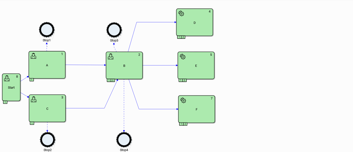
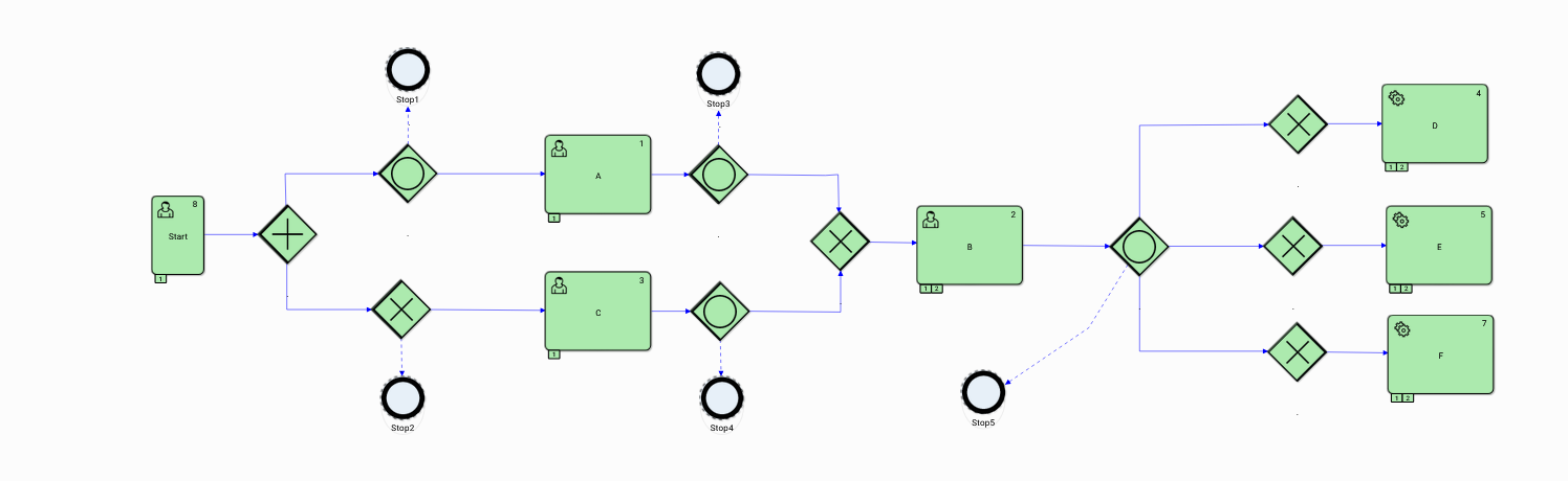
Figure 43. Run 1
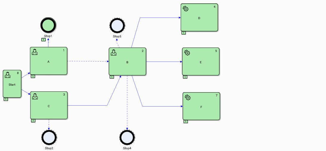
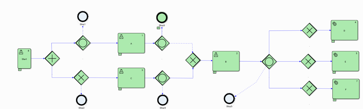
Figure 44. Run 2
Within the process instances of the second run executed after the condition $zn11 =false was specified*,* the path <Start, C, B, D, E, F> was executed. The second parallel path was interrupted for both instances at the exit flow stage A. It is easy to see that the interruption of the parallel process path after the execution of the instance of the action A will cause tasks <B, D, E, F> to be executed once.
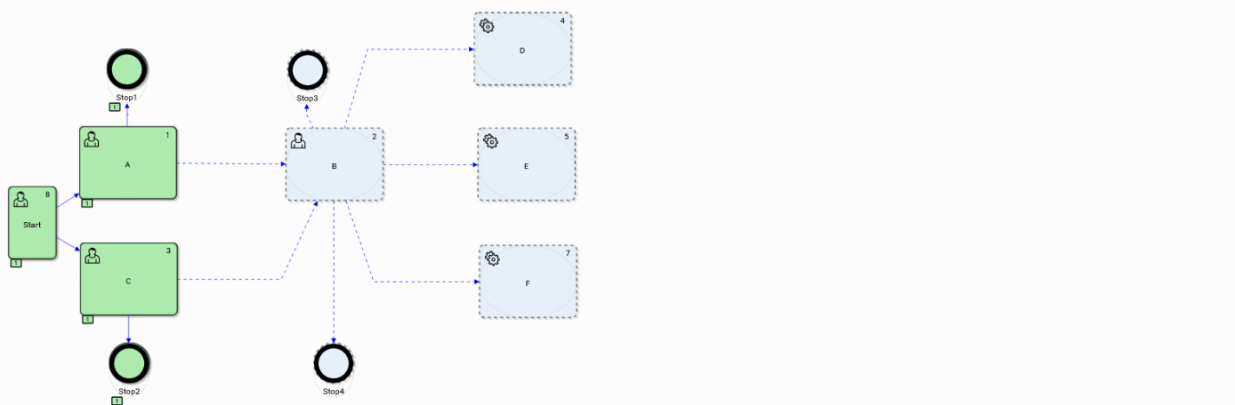
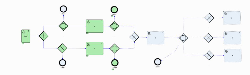
Figure 45. Run 3
The false values were specified for the logical variables $zn12 and $zn32. This configuration of flow conditions caused interruptions in both runs after the execution of tasks A and C. In the case of modeling the exit condition of task A, the default flow was used.
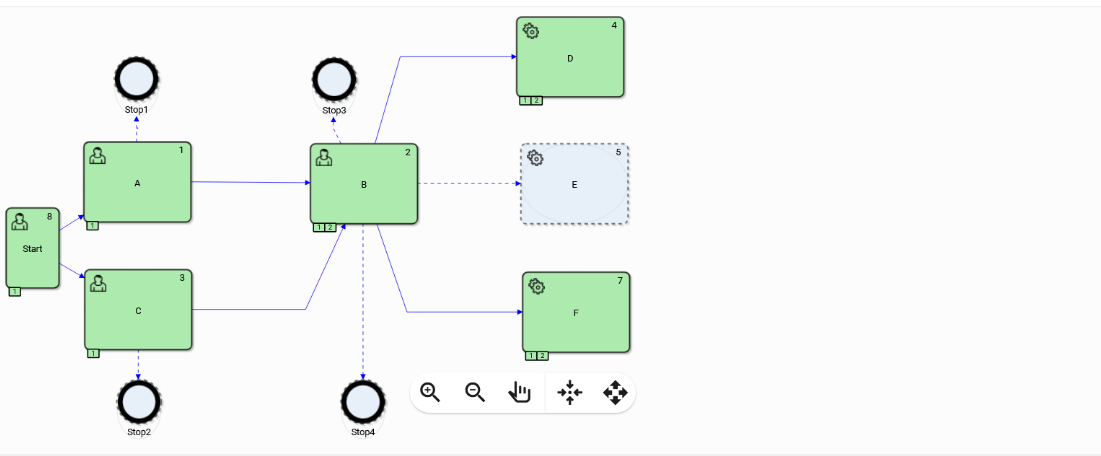
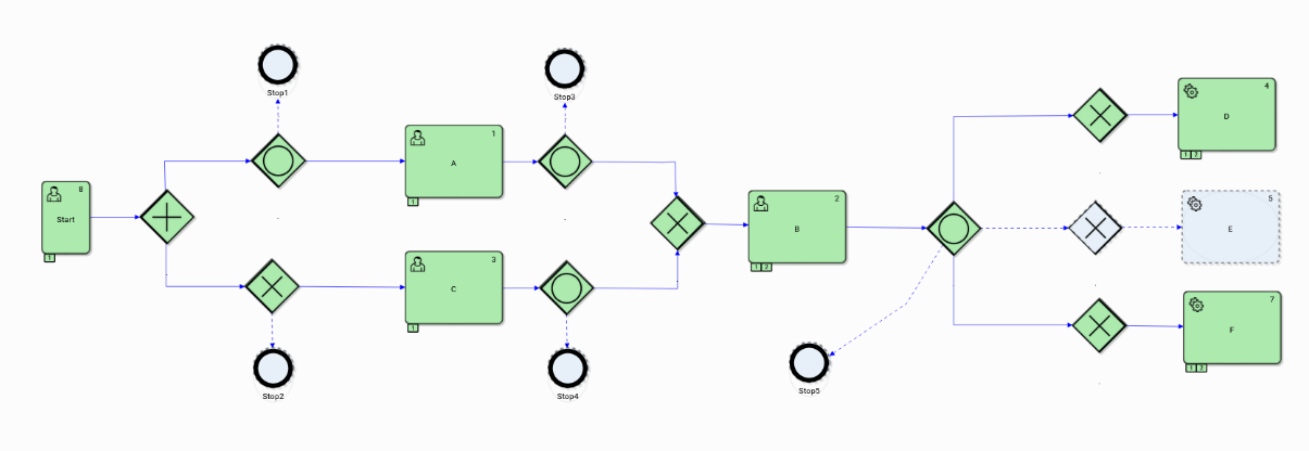
Figure 46. Run 4
In the fourth run, the value of the logical variable zn22=true was specified*,* which caused rejection due to the entry condition for task E. In the instances of both models, this activity was not performed.