
Introduction
docuRob ® Workflow platform was created based on many years of research and development work, the starting point of which was the OfficeObjects ® system software and the results of the Object Management Group standardization work in the field of BPMN 2.02 notation. An additional important starting element for work on the new platform architecture was the implementation of the Topic Maps model (ISO 23250) used to model the semantic resources of the modeled processes.
The result, which is schematically presented in Figure 1, is an intelligent platform for modeling and managing business processes, based on technical solutions such as:
- Graphical process model of to the process execution history compliant with BPMN 2.02 notation.
- An open information model covering process data and integration tools based on API (Rest, SOAP) and query languages (SQL, XPath) enabling the creation of application domain-specific functions extended with data from integrated IT systems.
- Internal model of process data management based on BPQL (Business Process Query Language) BPQL
- Representation of the process model in the WfMC ( Workflow Management Coalition ) notation supporting the export and import functions of process models.
- A subsystem for representing process ontologies, enabling direct access to semantic resources ( Topic Maps ) used by process instances.
The process information model includes data, both internal and external, which, as the execution context of the process instance, allow for controlling its execution based on the results of evaluation of the process execution rules implemented by BPQL comprising expressions and functions. The open set of functions allows users of the system to flexibly and easily extend their set. BPQL functions are implemented in the Java programming language and made available as part of the metadata resources of the docuRob ® WorkFlow platform in accordance with the DSL (Domain-specific language) DSL specification.
Data typically defined during process modeling include types such as global variables placed in the process data container, local variables, and input/output variables. As well as process parameters. Electronic Forms, used as a graphical user interface, are an additional source of input parameters and a recipient of output parameters. Local variables appear within BPQL expression blocks and are not available after their execution.
BPQL rules use process data by referring to both their current values and to the values contained in the processing history of the process instance. Within BPQL expressions, you can also use references to external data and semantic resources exposed within process ontology objects.
The API ( application program interface ) of the docuRob®WorkFlow platform allows you to retrieve any external data from IT systems that use the processes managed within an integrated process environment.
In addition to the coordination function that allows for the automation of tasks and resource allocation, the docuRob® WorkFlow system is used in the environment of existing IT systems as an integration platform.
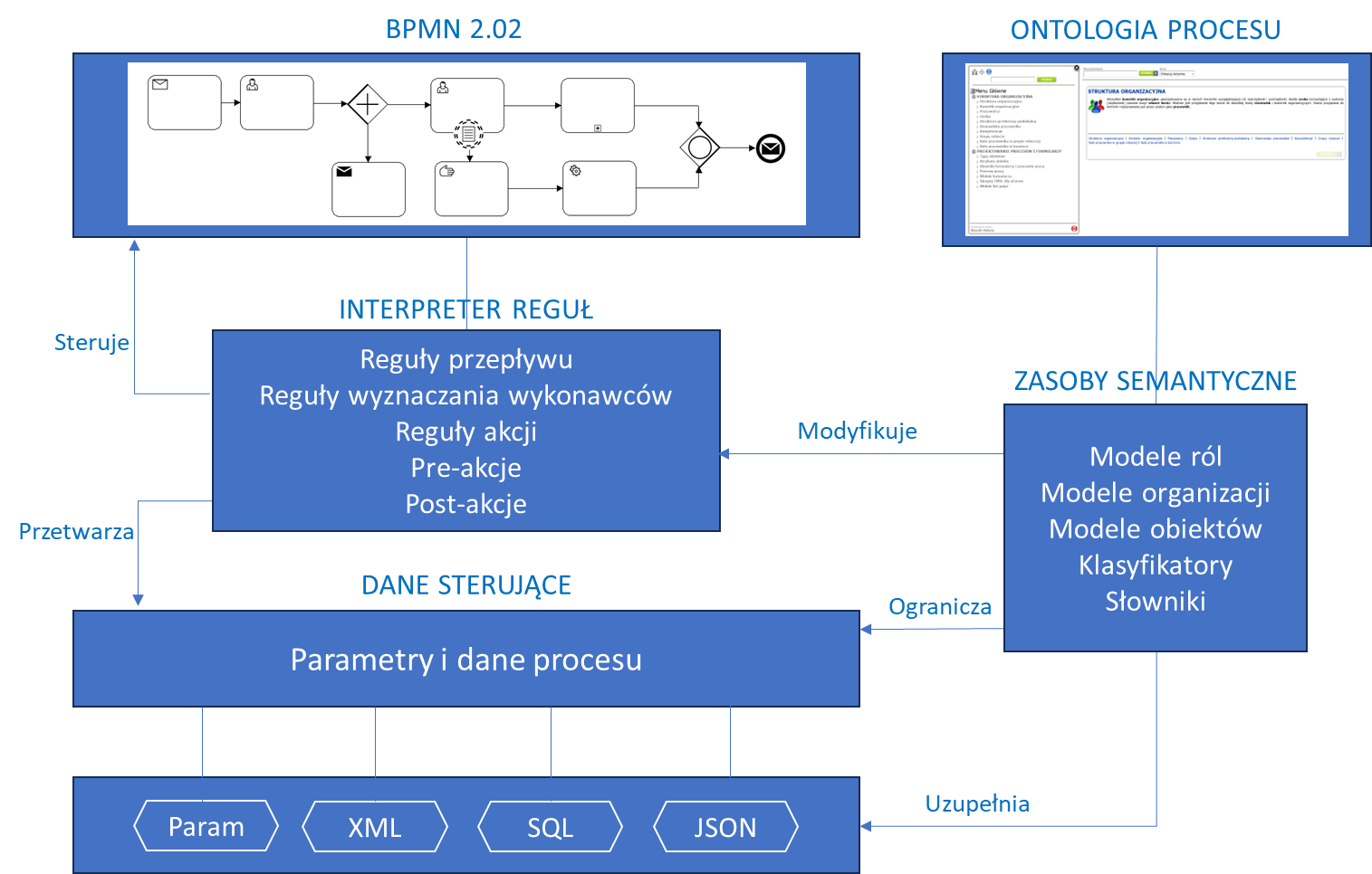
Figure 1. Information model of the docuRob®WorkFlow process
Conceptual data model of the process ontology
The process ontology is built based on the Topic Maps standard. A concept map is a set of knowledge elements corresponding to objects. Figure 2 presents the conceptual model of the process ontology.
A single object is represented as a concept (topic ) according to the Topic Maps notation. A concept is described by a set of names, attributes, concept classes, identifiers, and relationships with other concepts.
The set of concepts included in the topic map is divided into subsets of concepts belonging to a specific class. If a concept P belongs to class K, we say that the concept P is an instance of class K. The terminology also often used may be as follows “the concept P is of type K”. Topic maps also allow for class inheritance. If class X inherits from class Y, then the concept belonging to class X has the features of both classes X and Y.
The organization within which the process operates is represented by the Organizational Unit class. The organizational unit consists of organizational cells that can create any organizational structure of the unit.
Performers of manual tasks in the process or recipients of notifications generated by the process or process initiators are embedded in the organization's structure or are external participants of the workflow.
An employee of the organization that owns the process has a defined system account represented by the Person class, with which the Employee class is associated, representing relationships relevant from the point of view of the user's position in the organization.

Figure 2. Class diagram of the conceptual model of the process ontology
One person can work in different organizational units at different positions, so one user account ( Person ) can be associated with many Employees. An Employee must be associated with one person, position and one organizational unit.
A Workflow User can also be an external entity appearing in the diagram as the External Entity Account class.
Figure 3 shows an example employee Abacki Walenty (Senior specialist)/C. He is associated with the user account Abacki Walenty and is employed as a Senior specialist in organizational unit C.
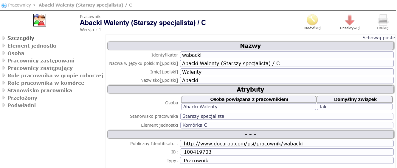
Figure 3. Sample Employee Details
In addition to being employed in a position in an organizational unit, an employee may also fulfill various roles in the organizational unit. Examples of employee roles in a unit may be: Invoice Approver, Leave Approver, etc.
On the one hand, there is the organizational structure of the company (connections of cells ), on the other hand, it is also possible to create working groups.
A working group is established for a fixed or indefinite period of time to perform a specific task. Employees belonging to a work group may have different roles within it. Examples of employee roles in a work group may be: Author, Reviewer, etc.
In addition to roles, there are also competencies in the system. The term role refers to the function that an employee performs in a specific context, while the term competency refers to the abilities or skills of a person that affect the effective performance of tasks. In essence, a role says what you do, and competency says how efficiently you do it.
Competencies are assigned in the system to a Person (user account). Examples of competencies include: knowledge of Spanish, knowledge of the European Union's sustainable development policies, etc.
Creating a working relationship between employees is useful and can be utilized in references to specific employees in the process, e.g. the next task should be performed by the superior of the current task participant, notification of a delay should reach the superior handling the matter, etc.
Employees can be linked to each other by Substitution relationships. An employee can be replaced by another employee and can replace yet another employee.
Ontology Concept Map Navigator
Topic Maps Navigator is a clear and flexible tool for presenting the process ontology. Figure 4 shows a general view of the Topic Map Navigator allowing for browsing and editing concepts and associations.
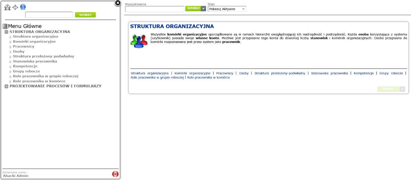
Figure. Concept 4 Map Navigator Overview
On the left side of the drawing is the Navigator menu, on the right side is the work area, which displays lists, hierarchies, or details of concepts. The concept map contains many topics that create various relationships between each other.
Concept sets are presented as lists or trees. An element of a list or a tree is a concept, visible as a link with a specific name. Clicking on a link displays information about the concept. Relations to other concepts are visible as links. The user can therefore navigate the entire map using the relationships between concepts.
The Main Menu contains two submenus: Organizational Structure and Process and Form Design.
The following items are displayed under the Organizational Structure menu item:
- Organizational Structure – displays the organizational structure tree
- Organizational units – displays a list of organizational units
- Persons – displays a list of people
- Employees – displays a list of employees
- Superior-subordinate structure – displays the hierarchy of reporting dependencies between employees
- Employee positions – displays the employee position dictionary (list of positions)
- Competencies – displays a list of relevant competencies
- Workgroups – displays a list of defined workgroups
- Employee roles in the Workgroup - displays a dictionary of employee roles in the context of workgroups
- Employee roles in a cell – displays a dictionary of employee roles in the context of organizational units
Figure 5 shows an example of a simple hierarchy representing the organizational structure of ABC Company.
Definition of organizational structure
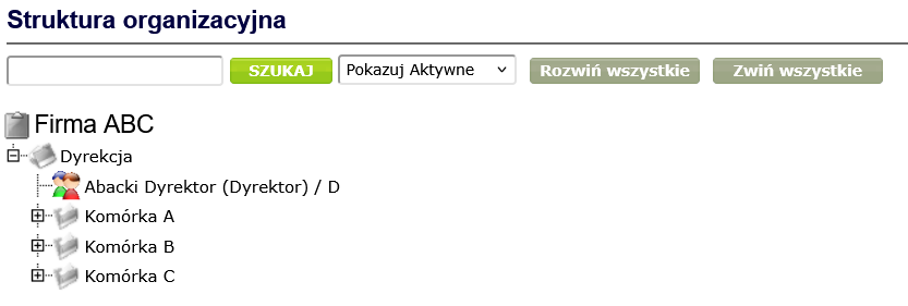
Figure 5. Sample organizational structure
You can switch the display in the box above the organizational structure to Expand all, which allows you to view all elements of the organizational structure ( Figure 6 ).
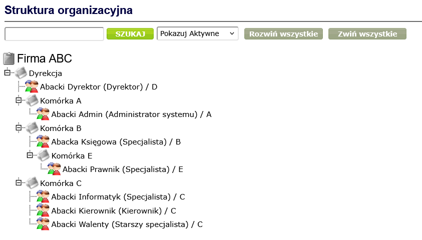
Figure 6. Organizational structure with expanded nodes
Selecting and clicking an organizational structure node displays a window with detailed information about the object represented by the node, which may be an organizational unit or an employee.
Figure 7 shows the details of the Cell B concept, which is an instance of the Organizational Cell class.
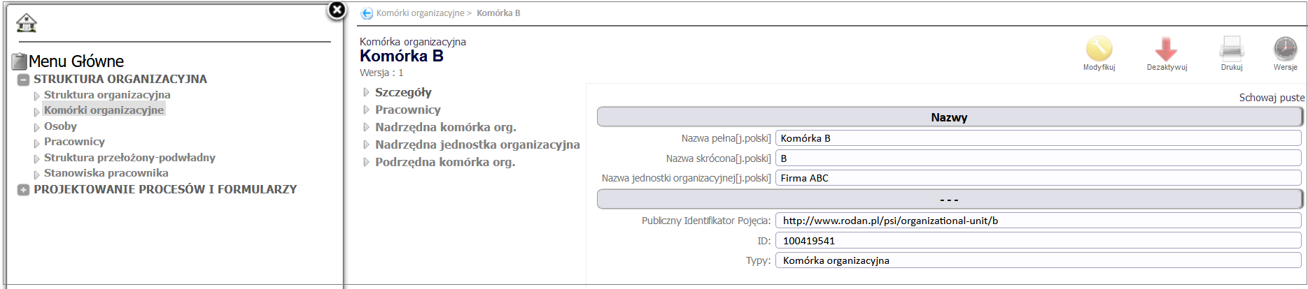
Figure 7. Details of the concept Cell B
The window with detailed information about the organizational unit provides the functionality for editing information, modifying the cell's connections with parent and child units, as well as with the parent unit, and the cell's connections with employees.
Figure 8 presents a list of concepts of the Organizational unit class.
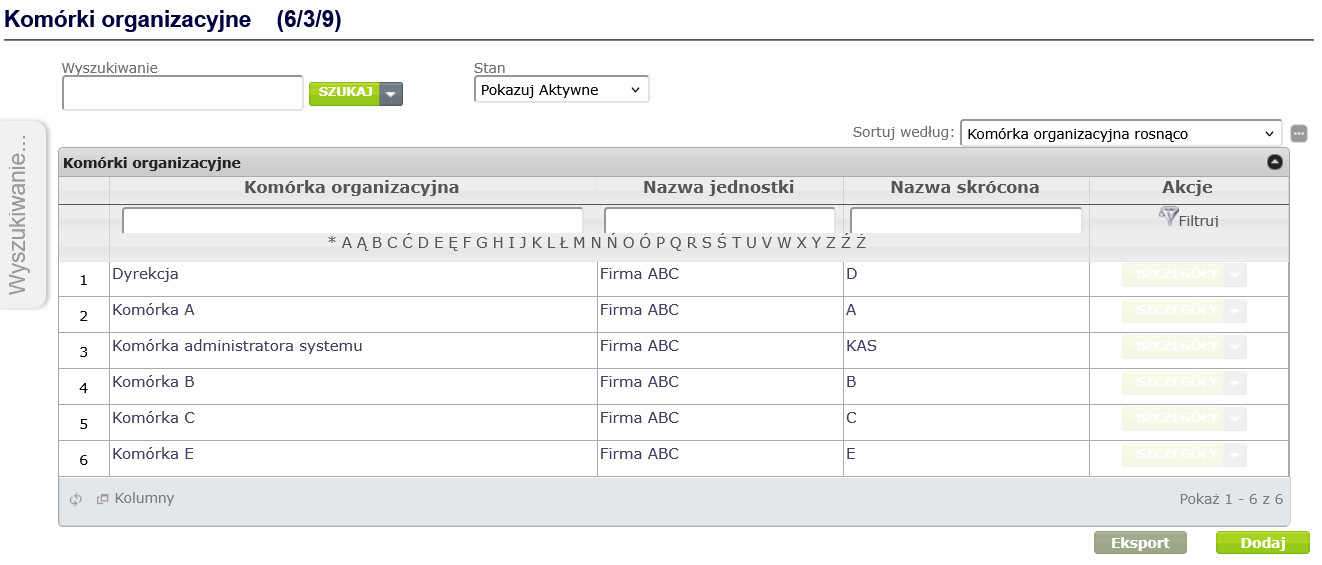
Figure 8. List of organizational units
Expanding the organizational structure involves creating organizational units and linking them together. To add a new organizational unit, click the Add button, fill in the mandatory fields, i.e. Full name and Short name, and then click the Save button ( Figure 9 ).
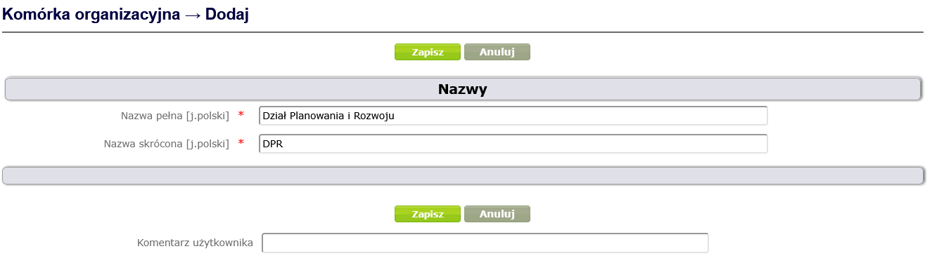
Figure 9. Creating the concept of the type Organizational unit
The newly created cell will appear on the list of organizational cells. Clicking on its name displays the details of the concept along with a context menu that allows you to link the cell to other cells or an organizational unit. The newly added Planning and Development Department cell is to be subordinate to the Management cell, so it will be linked to it. To do this, click the Parent org. cell item, select the Add button in the displayed window ( Figure 10 ), and then in the new Organizational cell association -> Add window, select the cell in the Parent org. cell field and click the Create button ( Figure 11 ).
If you want the newly added cell to be at the top of the hierarchy, select Parent organizational unit from the context menu to link it to an organizational unit
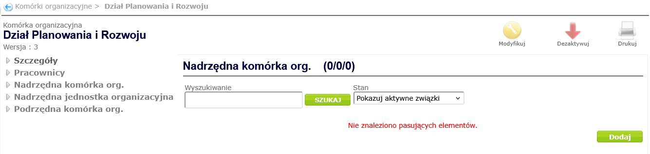
Figure 10. Adding a relationship between an organizational unit and a parent unit
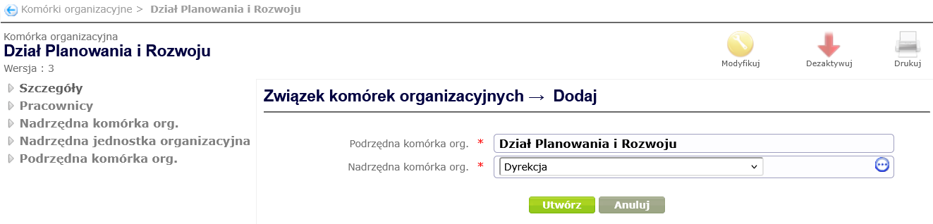
Figure 11. Creating a relationship between an organizational unit and a superior unit
In the next step, we will introduce a change in the organizational structure, which means that cell A will be a subordinate cell to the Planning and Development Department cell. An organizational cell can only have one superior cell or unit. Therefore, first deactivate the relationship between cell A and the superior cell (red arrow in the row containing the superior organizational cell - Figure 12 ) by confirming the deactivation with the Yes button, and then add the relationship between this cell and the superior cell (select Parent org. cell from the context menu, click Add, then select the superior cell from the dictionary and click Create - Figure 13 ).
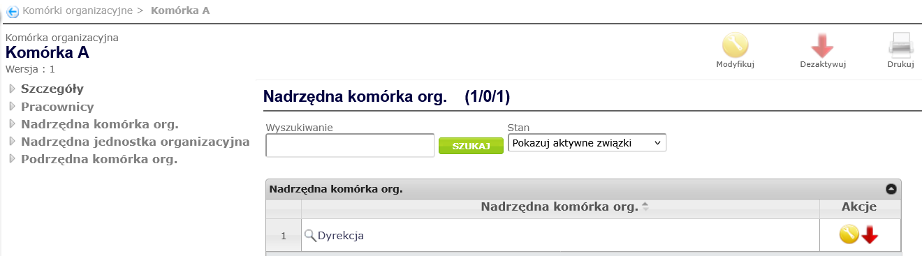
Figure 12. Deactivation of the cell's relationship with the superior organizational unit
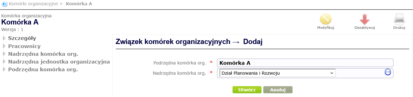
Figure 13. Creating a relationship between an organizational unit and a superior unit
Figure 14 presents the organizational structure of the unit changed as a result of the above actions.
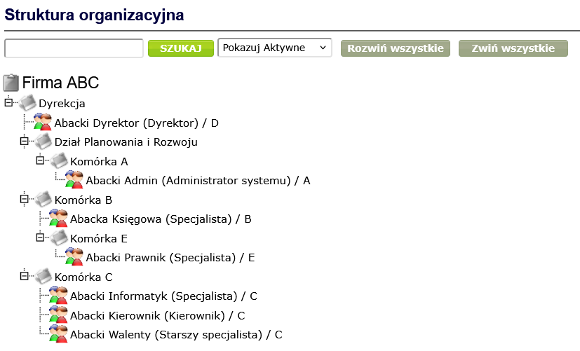
Figure 14. Example of organizational structure after changes
Definition of process users
Adding new users, employees of the organization, consists in creating a Person ( a Person type concept) and an Employee ( an Employee type concept ) associated with it. To add a new Person, select the Persons item from the Navigator menu, and then click the Add button located under the displayed list of people ( Figure 15 ).
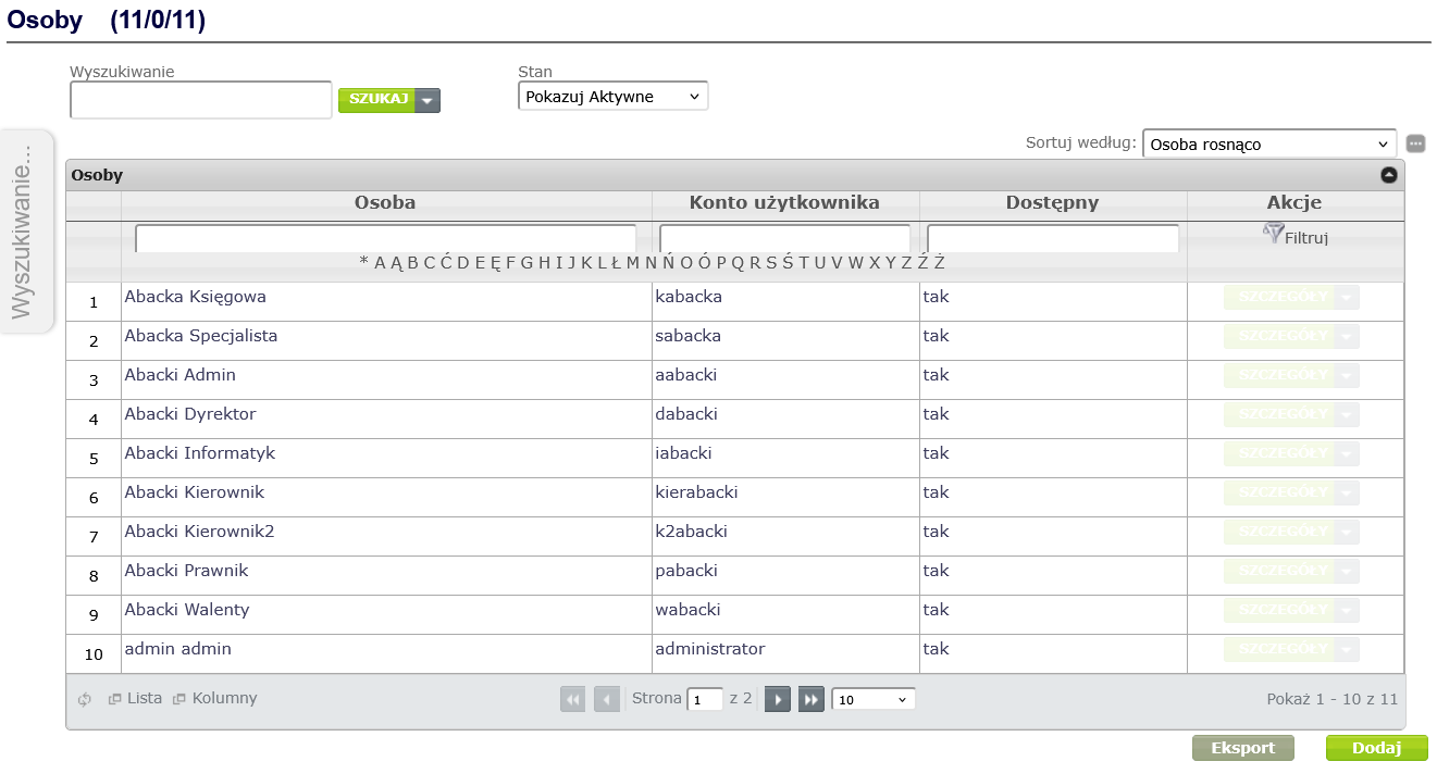
Figure 15. Adding a new Person
In the displayed window for creating a concept of the Person type, complete the following mandatory fields marked with asterisks:
- User account – i.e. login. User account cannot contain spaces. Allowed characters in the account name are: A...Z a...z 0...9 _ -.
- Password - the password can be entered manually or generated automatically using a password generator.
- Name
- Last name
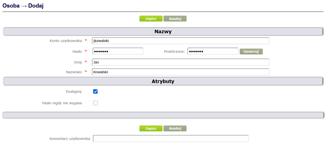
Figure 16. Creating the concept of the Person type
Available checkbox is set to True by default.
It is possible to enable the Password never expires option, which means that the password validity period parameter does not affect the user's need to change the password.
After clicking the Save button, the following fields are automatically filled: ID, which stores the numerical identifier of the topic, and the Public System Identifier ( PSI), and the newly created person appears on the list of people. Clicking on their name displays the concept details along with its context menu and icons that allow you to modify or deactivate the concept ( Figure 17 ).
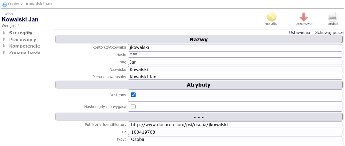
Figure 17. Details of an example concept of the Person type
There are 4 icons in the upper right corner of the screen. Clicking the "Deactivate" icon ![]() deactivates the displayed concept. An inactive person cannot log into the system and is not visible on the list of people. To display them, you need to change the people display parameters - to "Show Inactive". To restore a person to active, click the "Activate" icon,
deactivates the displayed concept. An inactive person cannot log into the system and is not visible on the list of people. To display them, you need to change the people display parameters - to "Show Inactive". To restore a person to active, click the "Activate" icon, ![]() which will be displayed in the upper right corner of the person details screen (in place of the "Modify" and "Deactivate" icons).
which will be displayed in the upper right corner of the person details screen (in place of the "Modify" and "Deactivate" icons).
Clicking the "Modify" icon ![]() allows you to edit the person's details.
allows you to edit the person's details.
The above rules for activating, deactivating and modifying concepts apply to all concepts for which the administrator has appropriate permissions in the Concept Map Navigator.
After creating a Person, you must define the Employee and optionally the competencies for them. To create an Employee for a given person, select the Employees item from the context menu of that person, and then click the Add button. In the window for creating a concept of the Employee type, fill in the mandatory fields ( Figure 18 ):
- in the ID field, enter the unique employee ID,
- select Yes in the Default Relationship field,
- select a position in the Employee Position field,
- select an organizational unit in the Unit Element field.
The Person associated with the employee field is automatically filled in by the system.
Finally, click the Save button.
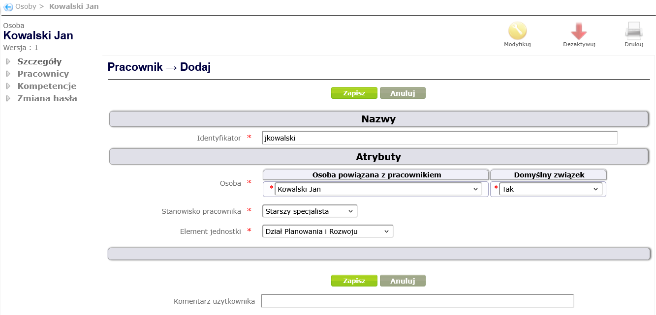
Figure 18. Creating a concept of the type Employee
Figure 19 shows the organizational structure tree after the above changes have been introduced.
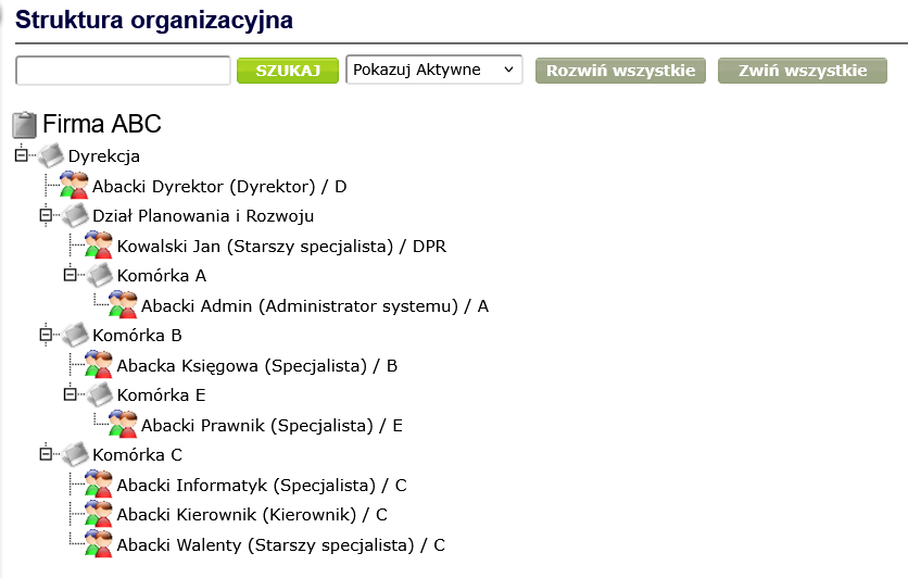
Figure 19. Changed organizational structure with employees
Employees are linked to each other by a superior-subordinate work relationship. In order to map such relationships in the system, select the Superior or Subordinate item from the context menu of the Employee type concept.
We will create such a relationship for the director by selecting the Subordinate position and then clicking the Add button. In the window for creating a relationship between a superior and a subordinate ( Figure 20 ), select the employee from the dictionary in the Subordinate field, and then click Create.
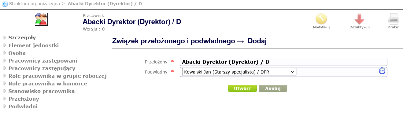
Figure 20. Creating a relationship between superior and subordinate
In this way, you can add supervisor-subordinate relationships from the context of each employee, keeping in mind that an employee can have only one supervisor but many subordinates.
Figure 21 shows an example reporting structure.
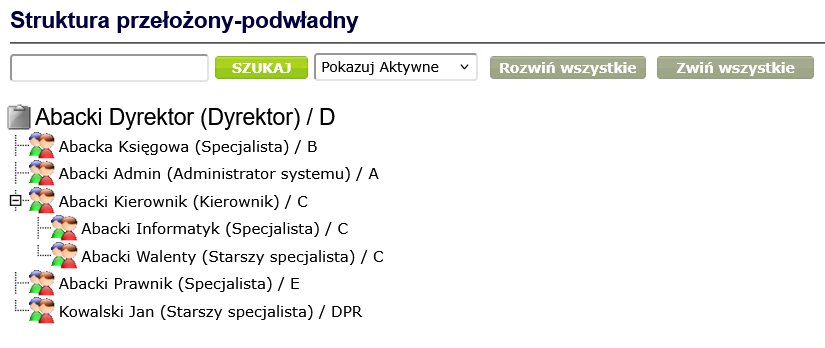
Figure 21. Superior-subordinate structure
To create a new competency, select Competencies from the Navigator menu and click the Add button in the work area ( Figure 22 ).
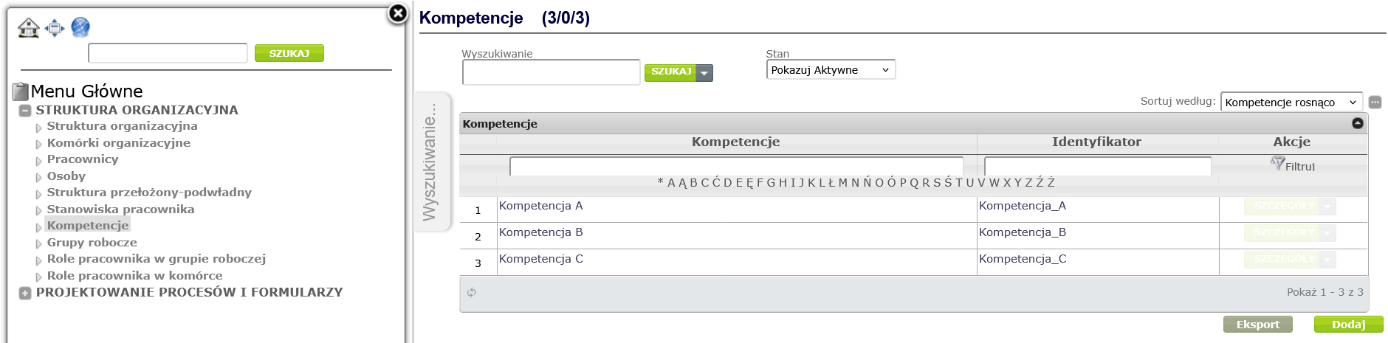
Figure 22. Adding competencies
In the window for creating a Competence type concept ( Figure 23 ), fill in the mandatory fields: Name and Identifier, optionally you can fill in the Description field, and then click the Save button.
Please note that identifiers should not contain spaces, special characters. Allowed characters are: A...Z a...z 0...9 _ -.
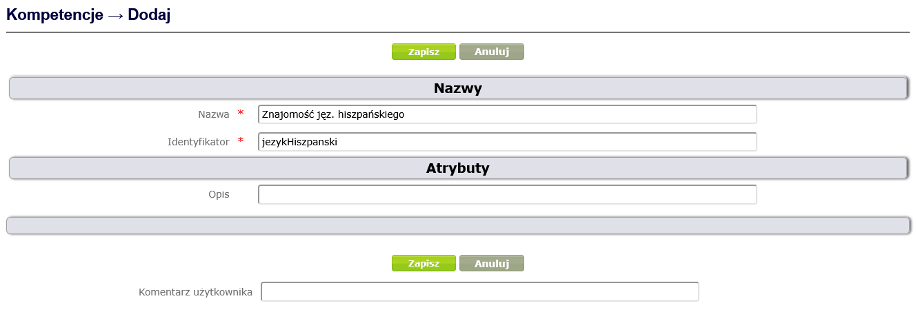
Figure 23. Creating a concept of the Competence type
After saving a competency, it appears on the competency list. Clicking on its name displays a window with details and a context menu ( Figure 24 ).
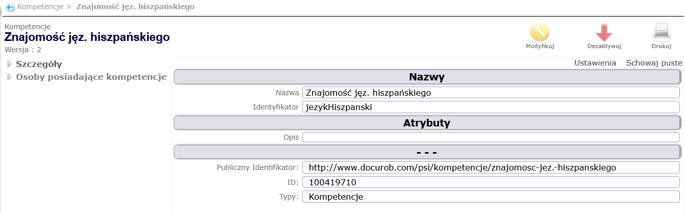
Figure 24. Details of competencies Knowledge of Spanish
To associate a competency with a person, select Persons with competencies from the context menu, then select the person and click the Create button ( Figure 25 ).
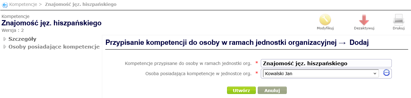
Figure 25. Assigning competencies to a person
The person for whom the association was created appears in the list of people with a given competence ( Figure 26 ).
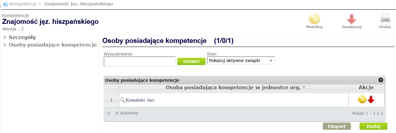
Figure 26. List of people with a specific competence
Definition of working groups
Workgroups can be established to perform specific tasks/projects. To create a new workgroup, select Workgroups from the Navigator menu and click the Add button in the workspace ( Figure 27 ).
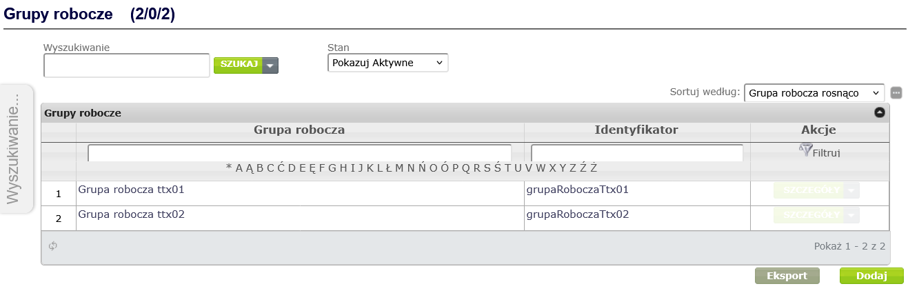
Figure 27. Adding a workgroup
Workgroup concept creation window ( Figure 28 ), fill in the mandatory fields: Name and Identifier, optionally you can fill in the Description field, the start and end dates of the group's work or check the box indicating that the group is established for an indefinite period, and then click the Save button.
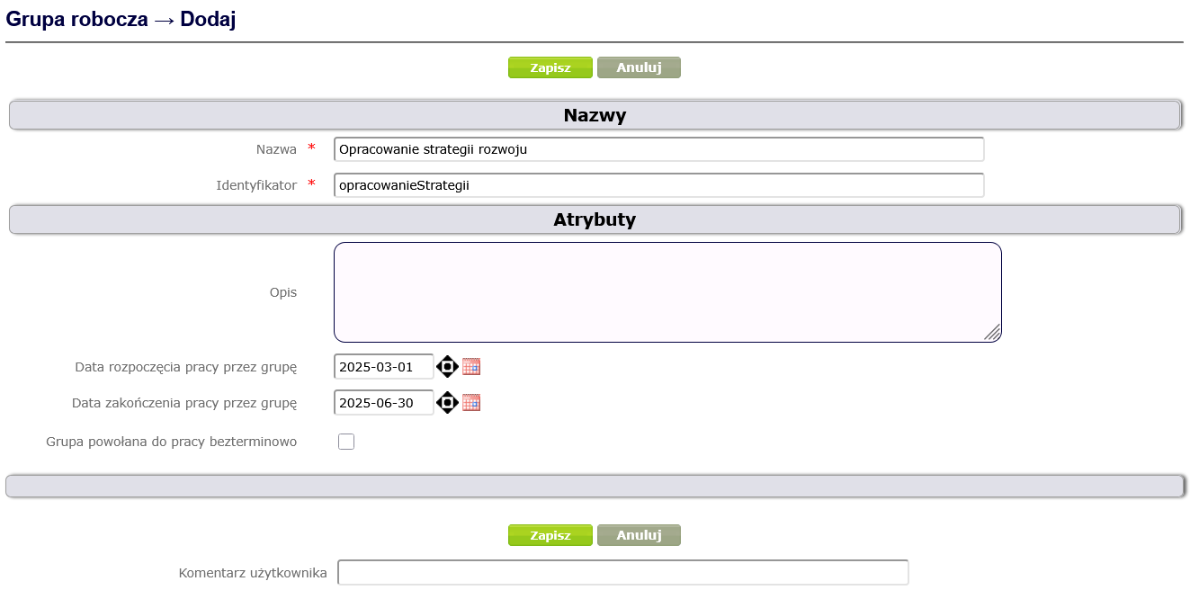
Figure 28. Creating a Workgroup type concept
Definition of process user roles
Employees can have different roles within a workgroup. To create appropriate roles for a workgroup, select Employee Workgroup Roles from the Navigator menu and click the Add button in the workspace ( Figure 29 ).
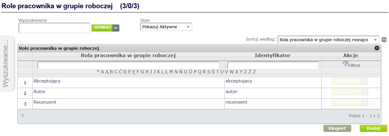
Figure 29. Adding an employee role in a workgroup
In the window for creating a concept of the Employee role in a workgroup type ( Figure 30 ), fill in the mandatory fields: Name and Identifier, optionally you can fill in the Description field, and then click the Save button.
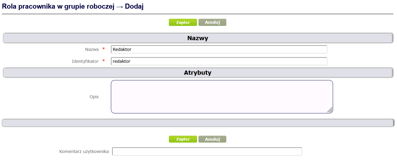
Figure 30. Creating a concept of the type Employee role in a work group
Assigning an employee in the appropriate role to a specific work group can be done both from the selected employee's side and from the selected work group's side. From the work group's side : After displaying the work group details, select Employees from the context menu and click the Add button in the work area ( Figure 31 ).
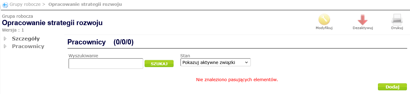
Figure 31. Adding employees to a workgroup
In the window for creating an employee-workgroup association ( Figure 32 ), complete the mandatory fields, i.e. select the employee in the Employee belonging to workgroup field and the role in the Employee role in workgroup field, and then click the Create button.
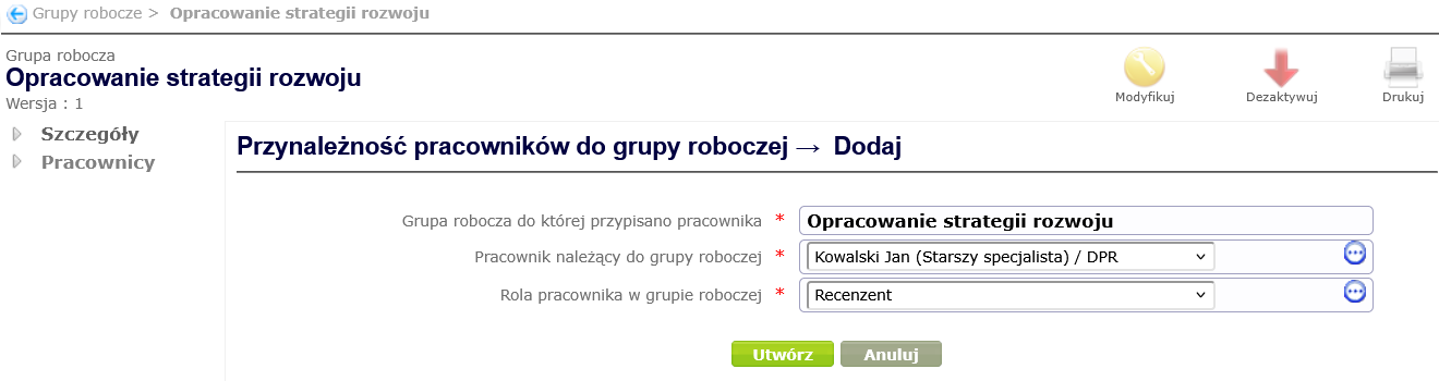
Figure 32. Creating a relationship between an employee and a work group
In addition to workgroup roles, employees can also have different roles within an organizational unit. To create roles for an organizational unit, select Employee Roles in Organizational Unit from the Navigator menu and click the Add button in the work area ( Figure 33 ).
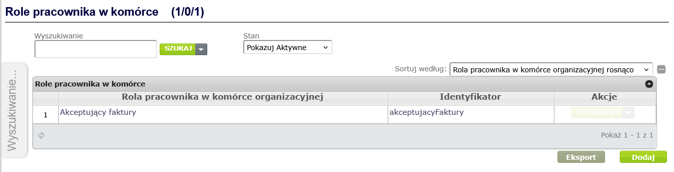
Figure 33. Adding an employee role in an organizational unit
In the window for creating a concept of the Employee role type in an organizational unit ( Figure 34 ), fill in the mandatory fields: Name and Identifier, optionally you can fill in the Description field, and then click the Save button.
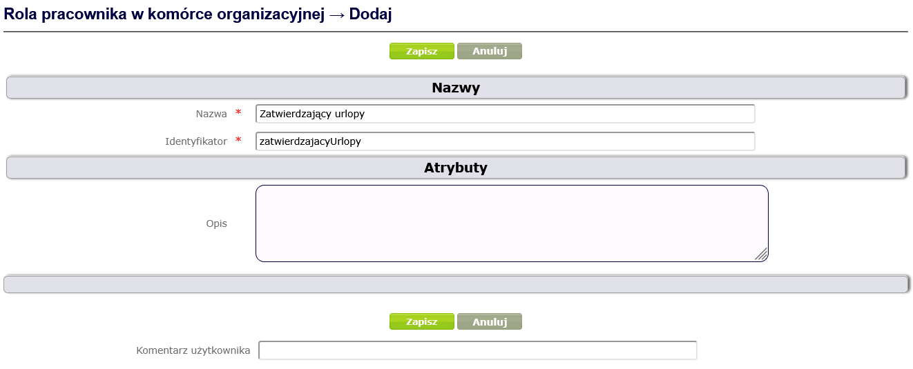
Figure 34. Creating the concept of the Employee's role in an organizational unit
To assign a role in an organizational unit to an employee, select Employee roles in organizational unit from the context menu of the selected employee and click the Add button in the workspace ( Figure 35 ).
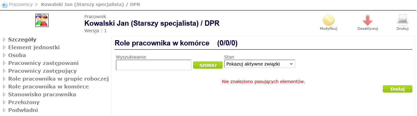
Figure 35. Assigning a role to an employee in an organizational unit
In the window for creating an employee-role relationship in an organizational unit ( Figure 36 ), select the role in the Employee role in the cell field, and then click the Create button.
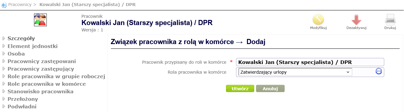
Figure 36. Creating a relationship between an employee and a role in an organizational unit
Definition of employee replacements
Employees can be replaced or substitute other employees. To assign a replacement to an employee, select Substituting employees or Substituted employees from the employee's context menu, and then click the Add button in the work area ( Figure 37 ).
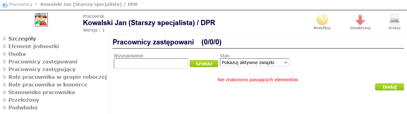
Figure 37. Adding a substitute employee
In the window for creating a replacement, select the replacing employee (when adding replacing employees) or the replaced employee (when adding replaced employees) from the dictionary and click the Create button ( Figure 38 ).
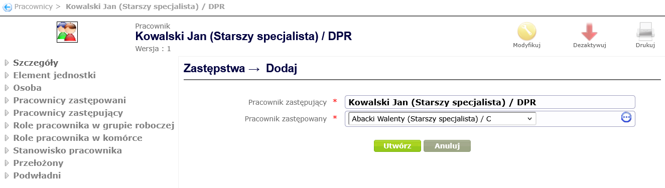
Figure 38. Creating a Substitution